diy solar

diy solar

Complete guide for 48V using EG4 18k

You can just tap off the input to the 18kpv and feed the transfer switch, as long the length of the run from the tap through the transfer switch and to the 70 amp breaker in the "off grid panel" is less the 25ft(we are using the 25ft tap rule for this).

Awesome, thanks! I wasn't aware of the 25' rule, but the run from the Grid Connected Subpanel to the 18k would be approximately 10'. I just bought some of these to split power to the 18K and transfer switch: https://www.amazon.com/gp/product/B09RD5DMM4

Or are you saying that I should put two of the 4AWG cables into the Grid Input of the 18K, one from the Grid Connected Sub panel, and one to the transfer switch, saving me a bit of money on the Polaris connectors? If so, I didn't think that was allowed, but I'm no electrician either. :)
No you can't put 2 wires into the lugs on grid input you'll have to use those "Polaris" connectors for the tap.
 
Is the installation eligible for the reduced protection rules on a feeder tap? Or was it presumed to be protected enough because of all the wireway in the picture.

Regarding leaking AC to the roof… 18kpv is I believe non isolated HF so it can still happen. The industry made the devils bargain long ago to go non isolated
 
Just bought the following bypass switch to add to the mix in the picture shown in my original post: https://www.amazon.com/gp/product/B008KNXJXE

I'm going to move the TIGO CCA into the wiring trough under the 18K and put this in its place where the TIGO box was on the wall, but then I got to thinking about how I'd wire up the switch. It seems easy enough - the center lugs would feed the 70 amp breaker in the 'Off Grid Subpanel', Load Out from the 18k would feed the supply on one side of the switch, and the other side would come from the 70 amp breaker from the 'Grid-Tied Subpanel'...however what's the proper way to feed power to the Grid In on the 18K? Would I get a Polaris connector so that the 'Grid-Tied Sub panel' feeds both the inverter and one side of the switch, or am I supposed to get a second breaker to put into the grid tied Subpanel to feed the 18K?
OK I missed something in my fist reply to this, and I'm sorry for that.

The grid connection on 18kpv requires a dedicated breaker or fusible disconnect. While you can to the tap like I previously described, you would need to install a separate breaker or disconnect at the 18kpv grid input. Given your setup installing an additional breaker in the "grid-tied subpanel" for the grid input to the 18kpv, is likely the cleanest option. Additionally you will need to add the appropriate hasp to this input breaker so it can be locked in the off position, these are typically cheap breaker accessories that clip on, but are unique to the style of breaker used.
 
Is the installation eligible for the reduced protection rules on a feeder tap? Or was it presumed to be protected enough because of all the wireway in the picture.
The wireway and conduit meet the protection requirement for have a feeder tap.
 
OK I missed something in my fist reply to this, and I'm sorry for that.

The grid connection on 18kpv requires a dedicated breaker or fusible disconnect. While you can to the tap like I previously described, you would need to install a separate breaker or disconnect at the 18kpv grid input. Given your setup installing an additional breaker in the "grid-tied subpanel" for the grid input to the 18kpv, is likely the cleanest option. Additionally you will need to add the appropriate hasp to this input breaker so it can be locked in the off position, these are typically cheap breaker accessories that clip on, but are unique to the style of breaker used.
OK, so you're saying that though I'll have a 70A breaker in the Sub Panel that would feed one side of the bypass switch, I'd need to have a second 70A breaker also in the sub panel that separately feeds the 18KPV, and I'd need to put an interlock in place, so that only one of the 70A breakers would be on at any given time?

As of now, my plan was to just feed the Polaris tap from the single 70A double breaker from the sub panel and splitting each leg of that and the grid neutral via the Polaris connectors feeding the 18K and to the other to the grid side of the bypass switch.
NEC 2017 705.12(B)(1) requires a dedicated breaker for the connections from 18kpv, NEC 2017 705.22 requires it to be lockable in the open position. There's no need to have an interlock there as the bypass/transfer switch will only let one power source be used. Also the interlock may interfere with mounting the breaker accessories, to enable locking the breaker in the open position.
 
OK, in just 'talking it out', if I fed the Polaris connector from the 70A breaker and fed both the 18K and the grid side of the bypass switch, and I had the switch in "bypass mode", I could see the possibility of there being heavy loads in the off-grid panel, and then at the same time the batteries saying that they needed charging, so the 18K would also pull power from the same 70A breaker, possibly overloading the circuit and tripping the breaker.

If I had a 70A breaker dedicated to the 18K, and a 70A breaker dedicated to the bypass switch, I suppose that would eliminate the possibility of tripping the one breaker. Am I missing anything else / any negative impact (other than not meeting code?)
 
Does 705.12(B)(1) allow internal circuit breakers / OCPD to count?

EG on a microinverter string you can connect them directly to trunk cable. I've noticed on spec sheet that the microinverters state what built-in OCPD they have on AC side.

(I don't know if 18kpv has an internal one)
 
OK, in just 'talking it out', if I fed the Polaris connector from the 70A breaker and fed both the 18K and the grid side of the bypass switch, and I had the switch in "bypass mode", I could see the possibility of there being heavy loads in the off-grid panel, and then at the same time the batteries saying that they needed charging, so the 18K would also pull power from the same 70A breaker, possibly overloading the circuit and tripping the breaker.

If I had a 70A breaker dedicated to the 18K, and a 70A breaker dedicated to the bypass switch, I suppose that would eliminate the possibility of tripping the one breaker. Am I missing anything else / any negative impact (other than not meeting code?)
While the breaker would trip the wiring would be safe which is what the code is trying to do. SO this config would still be safe, just not completely code compliant.
 
While the breaker would trip the wiring would be safe which is what the code is trying to do. SO this config would still be safe, just not completely code compliant.
Ok, I just wanted to make sure that I wasn't missing some other possibility that could make it unsafe. In the end, I would never put it in bypass mode unless I was going to turn the inverter off to do maintenance or if it died etc, so I think all would be well, just not code compliant. :)

Also, random question - I kinda want to mount the bypass switch sideways (so the switch lever would be parallel with the floor) - just not sure if there's some odd rule that would disallow that. Any idea?
 
Does 705.12(B)(1) allow internal circuit breakers / OCPD to count?

EG on a microinverter string you can connect them directly to trunk cable. I've noticed on spec sheet that the microinverters state what built-in OCPD they have on AC side.

(I don't know if 18kpv has an internal one)
Yeah nothing in that section about where/how the breaker is accessible for that requirement. The 18kpv only has a breaker on load connection, nothing on line, or gen inputs. 705.22 does require a disconnect, but this could be shared across multiple inverters, The breaker inside the 18kpv doesn't meet the requirements of that section as opening the door to access the breaker exposes live terminals, and there doesn't appear to be lockable in the off position.
 
Ok, I just wanted to make sure that I wasn't missing some other possibility that could make it unsafe. In the end, I would never put it in bypass mode unless I was going to turn the inverter off to do maintenance or if it died etc, so I think all would be well, just not code compliant. :)

Also, random question - I kinda want to mount the bypass switch sideways (so the switch lever would be parallel with the floor) - just not sure if there's some odd rule that would disallow that. Any idea?
I don't see any rule that would prohibit that.
 
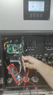
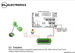
Here's one for you - not sure if you work for SS or EG4, or how well you know the 18KPV, but do you know if everything should work with just power from the batteries alone? For example, in trying to set up the RSD on the 18K, it doesn't appear that the +12 and -12 pins appear (per my multimeter) are hot.

I just wanted to get it powered up to get the latest firmware and an initial configuration on it before cutting over from the two 6500s.
I'm not really sure, is the display on? Also some of the early 18kpv units had a wiring issue that kept the 12volt out from working see this post: https://diysolarforum.com/threads/1...ustomer-use-on-a-eg4-18k-pv.68335/post-863369
 
I'm not really sure, is the display on? Also some of the early 18kpv units had a wiring issue that kept the 12volt out from working see this post: https://diysolarforum.com/threads/1...ustomer-use-on-a-eg4-18k-pv.68335/post-863369

Yeah the display is on and I was able to update the firmware via the mobile app, which is why I was a bit surprised to not see voltage on those two pins, so until I get that bypass switch in from Amazon and am ready to fully cut over thing over, I just moved the Tigo CCA into the trough and I'm powering it externally via a plug:

1697233316647.png

I could run some romex to the little transformer from a breaker, but if the 18k has some pins that provide 24v, I figured I'd use that instead.
 
(edit: For SunSpec RSD, I don't know about TIGO optimizer )There should be enough voltage on the DC string with RSDs shut down for a black start (assuming you have enough modules to stack up enough voltage)

So another way to ask this is whether 18kpv is smart enough to use this standby voltage for black start

That's good to know. Right now, I only have battery power to the 18Ks since the 6500's are still 'production' / have the solar strings connected. I'll likely do the full cutover next week after that bypass switch comes in.
 
Yes it will run from battery only.
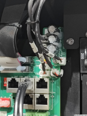
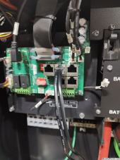
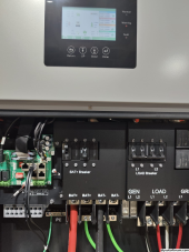
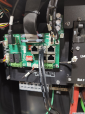
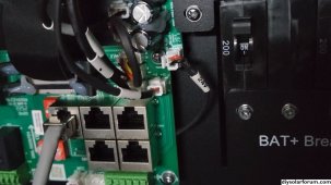
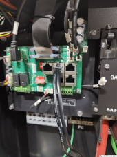
Here is the fix for your 24v RSD.
Pull the connector circled and plug into the -12 +12 port, leave the previous wire dangling.
 

Attachments

  • 24v connector.jpg
    24v connector.jpg
    763.9 KB · Views: 12
Back
Top