diy solar

diy solar

Complete guide for 48V using EG4 18k

And one more thing:

In my diagram, I do not attempt to show the locations of the disconnects. However, depending on the situation and the local rules, there may need to be additional 'readily accessible' disconnects in order to meet the NEC and/or local code requirements.
 
Yes, it is going back to the house, but it is not going to the PV racking system or PV frames. This is what I see in the pictures

View attachment 163109
Ahh, apologies, the other/panel side, I was not reading/looking carefully . If the PV panels are mounted to steel/conductive framing which is welded/directly attached to the metal post the box is on, just pull the wire from the earth ground and/or clamp it with a self-tap and lug onto the frame/post and tie it in. I would not run a separate ground conductor to the panels. I don't see the benefit, and it creates another ground path. I think you should try to avoid multiple ground paths as much as possible. It also appears on closer inspection the box is plastic. Validate ground with a meter between the frame on the farthest panel and the post near the box. If the PV frames are for some odd reason not mounted directly to a metallic suface I would ground each to the closest point that reaches the frame/metal, then ground the post to the green wire inside the plastic box. The earth ground is pointless.
 
Ahh, apologies, the other/panel side, I was not reading/looking carefully . If the PV panels are mounted to steel/conductive framing which is welded/directly attached to the metal post the box is on, just pull the wire from the earth ground and/or clamp it with a self-tap and lug onto the frame/post and tie it in. I would not run a separate ground conductor to the panels. I don't see the benefit, and it creates another ground path. I think you should try to avoid multiple ground paths as much as possible. It also appears on closer inspection the box is plastic. Validate ground with a meter between the frame on the farthest panel and the post near the box. If the PV frames are for some odd reason not mounted directly to a metallic suface I would ground each to the closest point that reaches the frame/metal, then ground the post to the green wire inside the plastic box. The earth ground is pointless.
Just to fill in the gaps a bit more...

It's all metal on metal on metal. Every panel has metal mounting brackets to metal framing.

The grounding rod does have a self tapping screw into the panel mount framing, but the 6AWG green is only touching the frame metal if connected to the ground rod.

It is in a plastic junction box

If everyone is saying to just take the green wire directly to the framing and ditch the ground rod it wouldn't be that hard to get it there. Is that what you guys would recommend?
 
Ahh, apologies, the other/panel side, I was not reading/looking carefully . If the PV panels are mounted to steel/conductive framing which is welded/directly attached to the metal post the box is on, just pull the wire from the earth ground and/or clamp it with a self-tap and lug onto the frame/post and tie it in. I would not run a separate ground conductor to the panels. I don't see the benefit, and it creates another ground path. I think you should try to avoid multiple ground paths as much as possible. It also appears on closer inspection the box is plastic. Validate ground with a meter between the frame on the farthest panel and the post near the box. If the PV frames are for some odd reason not mounted directly to a metallic suface I would ground each to the closest point that reaches the frame/metal, then ground the post to the green wire inside the plastic box. The earth ground is pointless.
The NEC code is a bit more stringent than that. Just being all metal on metal is not enough. They want a certified connection between the frame and the ground.
 
Folks. One thing about the 'simpler' diagram is that I should have shown the AC disconnect as a fused disconnect.

View attachment 163143


Another point is that the EG4 diagram shows a transfer switch. The transfer switch is a handy addition that allows you to bypass the inverter for maintenance.
Well, back to the drawing board round 100. I'm just not going to get these SolarEdge optimizers working without the SE inverter, I don't want to get on the roof as a general goal.

I think I'm going to have to go the AC coupled route for my SolarEdge setup. I wrote it off initially to decrease points of failure and to keep my generator...but here I am full circle. Early in my research phase so bear with me. I also need to see if my SE7600H-US model can even handle frequency shifting...so much mixed information there. I will poke around in the settings more when I get home.

BUT, if I'm going the AC coupling route (and my SE inverter is capable) can it be as simple as this diagram?
 

Attachments

  • Untitled.png
    Untitled.png
    179.4 KB · Views: 52
Hi, in this setup, the Grid terminal is just left untouch or something is connected there? If possible can you share a diagram like this where one can see how cables connected on the actual terminals? Thank you
Sorry, I just noticed this question.

For a total off-grid setup with the 18Kpv, there are actually a few ways to wire the inverter Grid and Gen ports.
  • If there is no generator, just leave the Grid terminals unconnected. The generator terminals can be used for a smart-load or for AC coupling. (I would think AC coupling would be a bit unusual for a completely off-grid system.)

  • If there is a generator, there are two ways to go
    1. Leave the Grid Terminals empty and hook the generator to the Gen terminals
    2. Hook the generator to the grid terminals and set the system as a Micro-Grid. The generator terminals can be used for a smart-load or for AC coupling.
 
Hi, in this setup, the Grid terminal is just left untouch or something is connected there? If possible can you share a diagram like this where one can see how cables connected on the actual terminals? Thank you
Here are diagrams showing the two different methods.

OPTION A
This one has the generator going to the Gen ports
1694974721902.png


OPTION B
This one has the generator going to the Grid ports. (The system MUST be set to Microgrid)

1694974891087.png

If there is no need for AC coupling or Smart load, I would use option A. I have no strong reason for that other than it is a bit more straightforward


Also notice that I added grounding to the batteries that I had previously left off.
 
Since the original design, the owner has decided to use the new outdoor wall mount batteries instead. I will have him wire it this way:

1694981136175.png

A couple of things to note:
  • Since there are only two batteries I will have them each wired directly to the inverter. This eliminates the need for the parallel kit and it will provide a more even balance of the current.
  • I am still deciding how to wire in the buck converter. (EG4 tells me they are working on providing connectors for this type of situation so I have not yet investigated it very deeply)
 
BTW: Here is a slightly updated diagram.

1) Added the current transformers. (These come with the 18Kpv)
2) Added the CANbus cable to the batteries (This also comes with the 18Kpv).

View attachment 161439
This might also be in line with the "code requirements" but in lieu of the 175A t-class fuses between the battery bank and the inverter does the internal battery breaker on the 18K serve as this?
I just installed virtually this same exact system and have yet to fire it up. Waiting on the electrician to finish installing all the outlets and fixtures
 
Last edited:
Yes, it is going back to the house, but it is not going to the PV racking system or PV frames. This is what I see in the pictures

View attachment 163109

Any connection between the EGC from the house and the panel frames is incidental at best.

It needs to be more like this:
View attachment 163110

How the ground is connected to the rack and PV frames is going to depend on the racking system. Given the description of the installer, and how the ECG from the house was handled, it is unlikely anything was done to properly bond frames and racking together.

Alright, I've had some time to finally sit down and figure out my "professionally installed" ground mount a bit further and I want to pick some more brains.

First off, here is the hardware they used:
solar.jpg
Oddly enough, it does have grounding clamps! After I saw that I ran outside with my voltage tester, and sure enough, there is continuity between every panel, between the racking, and between the bare copper cable going to the ground rod at the array.

That being said, the only place the bare copper wire contacts the array is through a single screw/cable management bracket holding the bare copper wire to the leg of the ground mount (you can see pictures on a previous page here)....so how I'm getting continuity after 5 years of corrosion I'm not sure.

My plan is now to disconnect everything from the ground rod, and re-route that bare copper wire to the racking/cross bar, use a washer designed to penetrate into the metal to attach the bare copper wire there. Then the 6AWG ECG goes to my inverter and I avoid the "two ground rods at different locations" dilemma.

Does all of that seem like a good approach to handling this? Is there any specific place I need to attach the bare copper ground wire to...or do I not need to stress too much considering I'm getting continuity everywhere? Most of the ground mounts I've seen have a dedicated ground lug, and I don't have that here.

Seems like I don't have as much work to do as I thought I did...which makes me happy.
 
Alright, I've had some time to finally sit down and figure out my "professionally installed" ground mount a bit further and I want to pick some more brains.

First off, here is the hardware they used:
View attachment 169903
Oddly enough, it does have grounding clamps! After I saw that I ran outside with my voltage tester, and sure enough, there is continuity between every panel, between the racking, and between the bare copper cable going to the ground rod at the array.

That being said, the only place the bare copper wire contacts the array is through a single screw/cable management bracket holding the bare copper wire to the leg of the ground mount (you can see pictures on a previous page here)....so how I'm getting continuity after 5 years of corrosion I'm not sure.

My plan is now to disconnect everything from the ground rod, and re-route that bare copper wire to the racking/cross bar, use a washer designed to penetrate into the metal to attach the bare copper wire there. Then the 6AWG ECG goes to my inverter and I avoid the "two ground rods at different locations" dilemma.

Does all of that seem like a good approach to handling this? Is there any specific place I need to attach the bare copper ground wire to...or do I not need to stress too much considering I'm getting continuity everywhere? Most of the ground mounts I've seen have a dedicated ground lug, and I don't have that here.

Seems like I don't have as much work to do as I thought I did...which makes me happy.
sounds about right
 
For anyone interested, here's an alternative install option that most people likely wouldn't do. My setup was a bit of an expensive experiment since I live in a neighborhood, with good power, and a whole house generator with ATS. Like the OP though, my intent was to just put a dent in my electric bill, since mine was creeping over $500/month. With my servers being pigs, and both AC units going along with the rest of the house loads, I've had 175Kwh days in the hotter months of July and August here in Virginia.

Recently I decided to upgrade to the 18K, since the 6500s wouldn't pass any sort of inspections where I live, and as I've posted before, I learned the hard way that they back feed power to the roof. Hopefully the 18K doesn't do that. :) I also wanted to take advantage of the lower power consumption, integrated RSD that actually powers the inverter(s) down (and it looks like the battery bank too if using the new LLv2s per some recent Signature Solar videos that they posted on YouTube), and make it so it doesn't sound like aircraft is taking off in my basement when the loads are high or there's a lot of solar (the 6500 fans are quite loud). Here's a bit more about my setup:

1696740612103.png

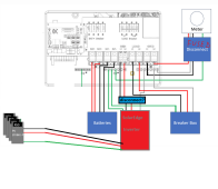
The panel to the right next to the battery bank is a Sub-Panel from my Main, located in another room with limited space that's 25' or so away. That grid tied panel currently feeds the two EG4 6500s with double pole 60A breakers. The inverters feed the off-grid panel that's to the left, where I moved the larger loads that I was trying to offset. In this case, it's both AC units, my servers, some freezers, my sump pump, a 50A outlet in my garage for my welder / plasma cutter, and my gym. As far as Solar goes, I have 15 REC Alpha 400 panels on the back of my garage broken into two strings, and eight of the SolarEver 410w panels on the front of my garage in a third string.

I decided to upgrade to the 18K via the upgrade program, even though I didn't really "need" it, though it's not operational as of yet - that's what it looks like as of tonight. I'm still waiting on my T-Class fuses (though I went with 250A) since I never did integrate them into the existing setup and figured during the cutover process, it'd be a good time to do it. BTW, I was going to mount the T-Class fuses in the trough under the 18k, but perhaps it's better to be closer to the battery bank?

Also, there's something I didn't catch BEFORE buying the 18K that has me a bit hesitant to put it 'in production' and that's the Zero Export feature not really being a true Zero Export. My goal was to never back feed the grid (I don't have a net metering agreement), but there's another thread that I found yesterday, started by @FilterGuy (though, I haven't finished reading through the whole thread yet). saying that it's possible to back feed power to the grid. In my case, I believe it'd should be fine, since any back fed power should power the constant loads that are on my main panel. If anyone disagrees or has any other input, please let me know.

I've not had any issues with the 6500s back feeding to the grid, at least that I could see via my Emporia App from the CTs in the main panel. I thought the 6500s were grid assist only, and just had bypass mode, but maybe they had the same issue, and I wasn't aware of it?

Once I cut over to the 18K, I'll have a double pole 70A breaker from the sub panel feeding the grid input on the 18k, and the 18k Load output will feed the 'Off-Grid Panel', also with a double pole 70A breaker, though the diagrams in the EG4 Manual appear to be incorrect if you need to round up from 62.5A - see highlighted below (it's also on several other pages):

1696742737294.png

After I cutover to the 18K, I'm probably going to just leave the 6500s on the wall and have them ready to go, should there be some sort of issue with the 18K and I needed to 'fail back'.

If anyone see's something I'm missing or issues with the setup (other than the AC / DC conductors in the trough under the 6500s not being separated, though I think in the 2023 NEC it's allowed now), or if you have any questions, please let me know.
 
Last edited:
Looks great. I’d probably double up the DC cables on the run to the 18k if you keep that distance. If you omit the 6500s I’d put a manual transfer switch to bypass the 18k just in case it croaks or needs servicing.
 
Zero Export feature not really being a true Zero Export.
Latest firmware and app gives you the option of putting it in genuine full off-grid mode, it will only attach to the grid when the batteries are in an oh shit state, even then it will not recharge the battery from grid unless you have a timer set up to do so. It just does a load pass through.
 
Looks great. I’d probably double up the DC cables on the run to the 18k if you keep that distance. If you omit the 6500s I’d put a manual transfer switch to bypass the 18k just in case, it croaks or needs servicing.
Yeah, I was considering the bypass transfer switch. Any particular brand you guys recommend? Just need to figure out where I'd put it on the wall. The space to the left of the 18K may be reserved for another 18k, if all goes well - not that I need it, but if I got an EV, I could see a use for it.

As far as doubling up, how do you mean? Go with two runs of 2/0 vs the 4/0 that I have? It's about 10' of cable to the batteries.
 
Last edited:
Latest firmware and app gives you the option of putting it in genuine full off-grid mode, it will only attach to the grid when the batteries are in an oh shit state, even then it will not recharge the battery from grid unless you have a timer set up to do so. It just does a load pass through.
Awesome, thanks for the info! Had no idea. Now I feel a bit better about proceeding with the install.
 
Last edited:
Awesome, thanks for the info! Had no idea. Now I feel a bit better about proceeding with the install.
You are going to love it compared to the 6500's, quiet as a church mouse until it's doing around 6kw of work in or out.
 
Just bought the following bypass switch to add to the mix in the picture shown in my original post: https://www.amazon.com/gp/product/B008KNXJXE

I'm going to move the TIGO CCA into the wiring trough under the 18K and put this in its place where the TIGO box was on the wall, but then I got to thinking about how I'd wire up the switch. It seems easy enough - the center lugs would feed the 70 amp breaker in the 'Off Grid Subpanel', Load Out from the 18k would feed the supply on one side of the switch, and the other side would come from the 70 amp breaker from the 'Grid-Tied Subpanel'...however what's the proper way to feed power to the Grid In on the 18K? Would I get a Polaris connector so that the 'Grid-Tied Sub panel' feeds both the inverter and one side of the switch, or am I supposed to get a second breaker to put into the grid tied Subpanel to feed the 18K?
You can just tap off the input to the 18kpv and feed the transfer switch, as long the length of the run from the tap through the transfer switch and to the 70 amp breaker in the "off grid panel" is less the 25ft(we are using the 25ft tap rule for this).

Edit: error in this replay see new reply below.
 
Last edited:
Back
Top