ksmithaz1
Solar / EV Junkie
Mike Holt / NEC Just watch some of his posts it will get clearer and clearer.


You are grounded whether you like it or not ?The structure itself is metal yes. Embedded in concrete. Does that change something?
Yup. I started to mention that earlier but decided not to add that complication to the conversation.You are grounded whether you like it or not ?
He said the green wire is running all the way back to the house. That should do the trick if it is grounded at the same point as all the other stuff/Yup. I started to mention that earlier but decided not to add that complication to the conversation.
With that big metal post going down into the earth, there is an earth-ground connection to the racking that can't be avoided. I would still remove the ground rod, but it probably does not make a lot of difference.
What is not happening is a proper ground connection from the house to the racking system. To be to code, that needs to be added.
Yes, it is going back to the house, but it is not going to the PV racking system or PV frames. This is what I see in the picturesHe said the green wire is running all the way back to the house. That should do the trick if it is grounded at the same point as all the other stuff/


 diysolarforum.com
Thanks for the upgraded diagram! This is much simpler than the diagram in the EG4 18k manual (not to mention much cheaper to implement). You have eliminated the feeder taps, the feeder tap breaker, the two pole manual transfer switch. Is all of that stuff really unnecessary?BTW: Here is a slightly updated diagram.

Folks. One thing about the 'simpler' diagram is that I should have shown the AC disconnect as a fused disconnect.Thanks for the upgraded diagram! This is much simpler than the diagram in the EG4 18k manual (not to mention much cheaper to implement). You have eliminated the feeder taps, the feeder tap breaker, the two pole manual transfer switch. Is all of that stuff really unnecessary?
I assume the PV interactive system 2-pole fused disconnect shown in the diagram works as the AC surge protection near the inverter that you mentioned above?
I assume everybody knows what diagram in the manual I'm talking about, but I'll add it so you don't have to look it up.View attachment 163135

Oh, I see. The feeder taps are needed for the transfer switch. Ok, so just making sure I understand this correctly: In the EG4 diagram the only real redundancy is the Main Service breaker followed by the 2-pole fused disconnect. From an NEC perspective, I can simply remove the main service breaker and replace it with the 2-pole fused disconnect where I would also bond my neutral and ground. Since my electrical co-op requires a "lever" disconnect at the service entrance, this setup should comply. Is that correct?Another point is that the EG4 diagram shows a transfer switch. The transfer switch is a handy addition that allows you to bypass the inverter for maintenance.
There are many ways to skin the cat. Depending on the situation, you might or might not decide to use feeder taps. In a retrofit, the feeder taps may be the best way to set things up. However, a new installation would probably be done differently and not use feeder taps even with the transfer switch.Oh, I see. The feeder taps are needed for the transfer switch. Ok, so just making sure I understand this correctly:
I am not sure I would say the Main service breaker and 2 pole fused disconnect are redundant. The feeder tap creates a 'y' in the circuit. Having an over-current device on each of the output legs is a good idea and I believe it is required by code.Ok, so just making sure I understand this correctly: In the EG4 diagram the only real redundancy is the Main Service breaker followed by the 2-pole fused disconnect.
That sounds correct. (I can't speak to the co-op requirements).From an NEC perspective, I can simply remove the main service breaker and replace it with the 2-pole fused disconnect where I would also bond my neutral and ground. Since my electrical co-op requires a "lever" disconnect at the service entrance, this setup should comply. Is that correct?
Ahh, apologies, the other/panel side, I was not reading/looking carefully . If the PV panels are mounted to steel/conductive framing which is welded/directly attached to the metal post the box is on, just pull the wire from the earth ground and/or clamp it with a self-tap and lug onto the frame/post and tie it in. I would not run a separate ground conductor to the panels. I don't see the benefit, and it creates another ground path. I think you should try to avoid multiple ground paths as much as possible. It also appears on closer inspection the box is plastic. Validate ground with a meter between the frame on the farthest panel and the post near the box. If the PV frames are for some odd reason not mounted directly to a metallic suface I would ground each to the closest point that reaches the frame/metal, then ground the post to the green wire inside the plastic box. The earth ground is pointless.Yes, it is going back to the house, but it is not going to the PV racking system or PV frames. This is what I see in the pictures
View attachment 163109
Just to fill in the gaps a bit more...Ahh, apologies, the other/panel side, I was not reading/looking carefully . If the PV panels are mounted to steel/conductive framing which is welded/directly attached to the metal post the box is on, just pull the wire from the earth ground and/or clamp it with a self-tap and lug onto the frame/post and tie it in. I would not run a separate ground conductor to the panels. I don't see the benefit, and it creates another ground path. I think you should try to avoid multiple ground paths as much as possible. It also appears on closer inspection the box is plastic. Validate ground with a meter between the frame on the farthest panel and the post near the box. If the PV frames are for some odd reason not mounted directly to a metallic suface I would ground each to the closest point that reaches the frame/metal, then ground the post to the green wire inside the plastic box. The earth ground is pointless.
The NEC code is a bit more stringent than that. Just being all metal on metal is not enough. They want a certified connection between the frame and the ground.Ahh, apologies, the other/panel side, I was not reading/looking carefully . If the PV panels are mounted to steel/conductive framing which is welded/directly attached to the metal post the box is on, just pull the wire from the earth ground and/or clamp it with a self-tap and lug onto the frame/post and tie it in. I would not run a separate ground conductor to the panels. I don't see the benefit, and it creates another ground path. I think you should try to avoid multiple ground paths as much as possible. It also appears on closer inspection the box is plastic. Validate ground with a meter between the frame on the farthest panel and the post near the box. If the PV frames are for some odd reason not mounted directly to a metallic suface I would ground each to the closest point that reaches the frame/metal, then ground the post to the green wire inside the plastic box. The earth ground is pointless.
diysolarforum.com
Well, back to the drawing board round 100. I'm just not going to get these SolarEdge optimizers working without the SE inverter, I don't want to get on the roof as a general goal.Folks. One thing about the 'simpler' diagram is that I should have shown the AC disconnect as a fused disconnect.
View attachment 163143
Another point is that the EG4 diagram shows a transfer switch. The transfer switch is a handy addition that allows you to bypass the inverter for maintenance.
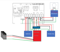
Hi, in this setup, the Grid terminal is just left untouch or something is connected there? If possible can you share a diagram like this where one can see how cables connected on the actual terminals? Thank you
Sorry, I just noticed this question.Hi, in this setup, the Grid terminal is just left untouch or something is connected there? If possible can you share a diagram like this where one can see how cables connected on the actual terminals? Thank you
Here are diagrams showing the two different methods.Hi, in this setup, the Grid terminal is just left untouch or something is connected there? If possible can you share a diagram like this where one can see how cables connected on the actual terminals? Thank you


This might also be in line with the "code requirements" but in lieu of the 175A t-class fuses between the battery bank and the inverter does the internal battery breaker on the 18K serve as this?BTW: Here is a slightly updated diagram.
1) Added the current transformers. (These come with the 18Kpv)
2) Added the CANbus cable to the batteries (This also comes with the 18Kpv).
View attachment 161439
Alright, I've had some time to finally sit down and figure out my "professionally installed" ground mount a bit further and I want to pick some more brains.Yes, it is going back to the house, but it is not going to the PV racking system or PV frames. This is what I see in the pictures
View attachment 163109
Any connection between the EGC from the house and the panel frames is incidental at best.
It needs to be more like this:
View attachment 163110
How the ground is connected to the rack and PV frames is going to depend on the racking system. Given the description of the installer, and how the ECG from the house was handled, it is unlikely anything was done to properly bond frames and racking together.
Grounding Made simpler - Part 3: Solar Panels
To get the paper, click on the orange button at the top of the screen. The subject of grounding is a complex, multifaceted subject, that is often treated as an after-thought but needs to be considered from the beginning of the design and build...

sounds about rightAlright, I've had some time to finally sit down and figure out my "professionally installed" ground mount a bit further and I want to pick some more brains.
First off, here is the hardware they used:
View attachment 169903
Oddly enough, it does have grounding clamps! After I saw that I ran outside with my voltage tester, and sure enough, there is continuity between every panel, between the racking, and between the bare copper cable going to the ground rod at the array.
That being said, the only place the bare copper wire contacts the array is through a single screw/cable management bracket holding the bare copper wire to the leg of the ground mount (you can see pictures on a previous page here)....so how I'm getting continuity after 5 years of corrosion I'm not sure.
My plan is now to disconnect everything from the ground rod, and re-route that bare copper wire to the racking/cross bar, use a washer designed to penetrate into the metal to attach the bare copper wire there. Then the 6AWG ECG goes to my inverter and I avoid the "two ground rods at different locations" dilemma.
Does all of that seem like a good approach to handling this? Is there any specific place I need to attach the bare copper ground wire to...or do I not need to stress too much considering I'm getting continuity everywhere? Most of the ground mounts I've seen have a dedicated ground lug, and I don't have that here.
Seems like I don't have as much work to do as I thought I did...which makes me happy.
") I also wanted to take advantage of the lower power consumption, integrated RSD that actually powers the inverter(s) down (and it looks like the battery bank too if using the new LLv2s per some recent Signature Solar videos that they posted on YouTube), and make it so it doesn't sound like aircraft is taking off in my basement when the loads are high or there's a lot of solar (the 6500 fans are quite loud). Here's a bit more about my setup:
I also wanted to take advantage of the lower power consumption, integrated RSD that actually powers the inverter(s) down (and it looks like the battery bank too if using the new LLv2s per some recent Signature Solar videos that they posted on YouTube), and make it so it doesn't sound like aircraft is taking off in my basement when the loads are high or there's a lot of solar (the 6500 fans are quite loud). Here's a bit more about my setup:

Latest firmware and app gives you the option of putting it in genuine full off-grid mode, it will only attach to the grid when the batteries are in an oh shit state, even then it will not recharge the battery from grid unless you have a timer set up to do so. It just does a load pass through.Zero Export feature not really being a true Zero Export.