diy solar

diy solar

Complete guide for 48V using EG4 18k

My thought I'm trying to work towards is to have the system use solar panels to power the house + charge enough battery capacity to power the house during the night which has much lower usage. Do you feel that would be a fools errand?
As a resident of the Phoenix Valley, I wonder how you plan on coping with the permit process? I installed a good sized system on my RV, but I am totally overwhelmed by the permitting system for the house. I could do all the installation but have no idea where to start with the permit.

Installing yourself will save you a lot of money.

As a resident of Phoenix Arizona, a lot of the suggestions being made will not save money, at least in the next 15 years, and often times the estimates are a little optimistic and don't take into account equipment breaking. That $600 a month bill is just two or three months for me an annual electric bill of $2200 is a big distractor to have solar installed at $15k per 5 kw of panels.

If you understand that and saving money is not your goal, then no its not a fools errand. I am in the process of getting a 10 kWh battery pack and a 10 kW solar array installed with an 8 kw Inverter, and rationally for the Phoenix area, that amount of money makes no sense for the payback period, especially with the record of years of uninterrupted power we have experienced.
 
I used to live in Phoenix. I upgraded my 15yr old heat pump to a new trane two stage, got the ducts redone, and had my attic insulated and I dropped my monthly utility bill 150/mo in summer
The house after that we had a 2 story with two units and our summer average was <50kwh in a day.
I’d definitely explore the window upgrade and other cost saving measures
One things for sure, I don’t miss the heat! Now I just typically yearn for oxygen instead hah
I agree with the upgrades. It's a fairly decent investment and will almost certainly help with resale down the road.
 
145kwh in a day is not so huge from my experience. He's in Phoenix area so as bad or worse than here in Texas. Before I upgraded my heat pumps I was hitting that much last year on hot days. Really cold winter days were much worse. We had a day last winter with 12F low and something like 22F high - I burned through 270kwh that day but the old heat pumps were VERY inefficient at heating. We'll see how the new ones do this winter. With the 105F to 107F temps we've had the last few weeks I've been hitting around 110 to 115 kwh per day, with 80kwh of that coming from solar. That's with adding a mini-split for the garage and two more freezers than last year, which tells me these mini-splits are really helping.

With a family and four kids I'm going to hazard a guess that @Jdcarrol has a decent size house so I'm not surprised at the usage. Older house even more so.
Lol, 4 kids in this house too!
 
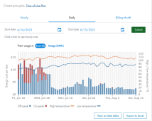
With your load, you will likely want another inverter, allow room for it. 14KW of batteries may not take you past 8PM in July, and will likely not provide sufficient current output for more than one inverter. Solar production really falls off around 1600hrs. I'm using a transfer switch instead of grid tie. I'm not sure where the weekly 1KW of "On-Peak" cost is coming from because I'm literally 100% disconnected from the grid between about 7:15 and at least 10PM. My next bill estimate is now $105. Last year my bill was $395, 60's block house, 1400sqft. I'd also like to know about the permitting/etc you are planning. I've been tweaking my setup to make sure it would pass if I decide to actually tie up. RSD is not currently required here, not sure if I want it, I have a DC breaker/surge panel outside. Putting RSD on/at all the panels is going to be as expensive as the panels (TIGO or something). I would put in a surge/DC breaker box for your strings, just for sanity/safety. It's cheap. I also would use an inline breaker/fuse from the batteries sized for the max load you actually want to pull. Keep in mind a fuse or a breaker may actually exceed it's rating for a significant amount of time before it blows/trips. I got the panels installed around July 3rd. Other than some HVAC startup issues which I finally got resolved it's been great. When the nite-time lows are under 90F with 30KWH I can make it until 0000hrs and beyond. If you start pushing electrons at SRP they will probably notice. I need more batteries, 30KWH is just not enough.
1692200129941.png
 
As a resident of the Phoenix Valley, I wonder how you plan on coping with the permit process? I installed a good sized system on my RV, but I am totally overwhelmed by the permitting system for the house. I could do all the installation but have no idea where to start with the permit.

Installing yourself will save you a lot of money.

As a resident of Phoenix Arizona, a lot of the suggestions being made will not save money, at least in the next 15 years, and often times the estimates are a little optimistic and don't take into account equipment breaking. That $600 a month bill is just two or three months for me an annual electric bill of $2200 is a big distractor to have solar installed at $15k per 5 kw of panels.

If you understand that and saving money is not your goal, then no its not a fools errand. I am in the process of getting a 10 kWh battery pack and a 10 kW solar array installed with an 8 kw Inverter, and rationally for the Phoenix area, that amount of money makes no sense for the payback period, especially with the record of years of uninterrupted power we have experienced.
I did the Solar thing for fun, and proof of concept. I also have 2-EV's, So I've been trying to figure out how to weave in charging them during the day to take advantage of the over-production. OpenEVSE has some fun gadgets I'll be playing with next. To the author's point . . .

Electricity in Phoenix, as much as it is outrageous in July/August, is REALLY inexpensive. No really, really. I think my annual electric bill isunder $3500/year. APS/SRP have plans that average your bill if you struggle in the summer. I will also say that most of the grid around here is underground, and extremely reliable, In the 15+ years I've been here I can count the number of times the power has been out on my fingers, and I don't recall any outage lasting over an hour. Complain all you want but these guys in this town are really very good.

That being said. I think all the green silliness is going to drive costs up. We are already seeing a significant increase scheduled for 2024, and I could be way wrong, but I really wouldn't be surprised to see rates go up as much as 30% over the next 5 years if cooler heads don't slow down some of the rhetoric and policy making. At which time, if you already have something in play your payback may accelerate. I spent around $30K and I need to add another $10 for more batteries. If I can get my annual bill below $1000/year I figure I'm getting a $2K/year payback. That is a 20 year ROI by the time I am where I want to be. Any rate increases (I can be sure it won't go down anyway) reduces the time, but it's really hard to recommend something like this simply because the power from the nuclear plant nearby is so inexpensive.

Next-gen solar panels and batteries may change this paridigm dramatically. There are technologies on the horizon that may garner another 50% increase in efficiency from panels, and I firmly believe we will see a doubling of battery capacity within the next 10 years. Based on my experience thus far with some older panels I picked up the newer 455's on my roof seem to be a lot more stable in terms of output, but I'm still playing with that as well.

Don't do this if you think you are going to save a bunch of money.
 
More updates to my grounding confusion.

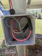
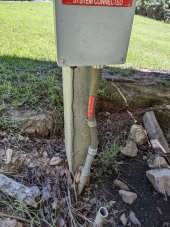
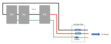
Opened up the ground mount junction box. It's literally just the ground rod tied into the conduit run ground 6 AWG wire to the house. There are a single screw joining the ground rod into the metal array mounts I guess?! (see second picture)

More confused then when I started. This is all "passed inspection" work from my original installers.

What should I do with this green wire running to the house? Part of me wants to just cap it and ignore it, and let the grounding rod here just be attached to the frame. into the earth?


1000012984.jpg1000012985.jpg
 
You are grounded whether you like it or not ?
Yup. I started to mention that earlier but decided not to add that complication to the conversation.

With that big metal post going down into the earth, there is an earth-ground connection to the racking that can't be avoided. I would still remove the ground rod, but it probably does not make a lot of difference.

What is not happening is a proper ground connection from the house to the racking system. To be to code, that needs to be added.
He said the green wire is running all the way back to the house. That should do the trick if it is grounded at the same point as all the other stuff/
 
He said the green wire is running all the way back to the house. That should do the trick if it is grounded at the same point as all the other stuff/
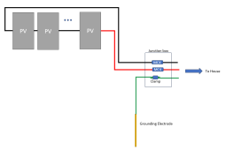
Yes, it is going back to the house, but it is not going to the PV racking system or PV frames. This is what I see in the pictures

1692230952500.png

Any connection between the EGC from the house and the panel frames is incidental at best.

It needs to be more like this:
1692231103946.png

How the ground is connected to the rack and PV frames is going to depend on the racking system. Given the description of the installer, and how the ECG from the house was handled, it is unlikely anything was done to properly bond frames and racking together.

 
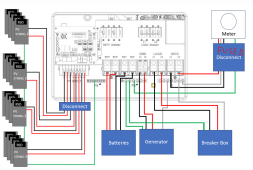
BTW: Here is a slightly updated diagram.
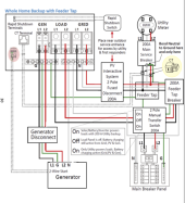
Thanks for the upgraded diagram! This is much simpler than the diagram in the EG4 18k manual (not to mention much cheaper to implement). You have eliminated the feeder taps, the feeder tap breaker, the two pole manual transfer switch. Is all of that stuff really unnecessary?
I assume the PV interactive system 2-pole fused disconnect shown in the diagram works as the AC surge protection near the inverter that you mentioned above?

I assume everybody knows what diagram in the manual I'm talking about, but I'll add it so you don't have to look it up.EG4-18KPV-12LV-Manual-1.3.0-p30.png
 
Thanks for the upgraded diagram! This is much simpler than the diagram in the EG4 18k manual (not to mention much cheaper to implement). You have eliminated the feeder taps, the feeder tap breaker, the two pole manual transfer switch. Is all of that stuff really unnecessary?
I assume the PV interactive system 2-pole fused disconnect shown in the diagram works as the AC surge protection near the inverter that you mentioned above?

I assume everybody knows what diagram in the manual I'm talking about, but I'll add it so you don't have to look it up.View attachment 163135
Folks. One thing about the 'simpler' diagram is that I should have shown the AC disconnect as a fused disconnect.

1692245380720.png


Another point is that the EG4 diagram shows a transfer switch. The transfer switch is a handy addition that allows you to bypass the inverter for maintenance.
 
Another point is that the EG4 diagram shows a transfer switch. The transfer switch is a handy addition that allows you to bypass the inverter for maintenance.
Oh, I see. The feeder taps are needed for the transfer switch. Ok, so just making sure I understand this correctly: In the EG4 diagram the only real redundancy is the Main Service breaker followed by the 2-pole fused disconnect. From an NEC perspective, I can simply remove the main service breaker and replace it with the 2-pole fused disconnect where I would also bond my neutral and ground. Since my electrical co-op requires a "lever" disconnect at the service entrance, this setup should comply. Is that correct?
 
Oh, I see. The feeder taps are needed for the transfer switch. Ok, so just making sure I understand this correctly:
There are many ways to skin the cat. Depending on the situation, you might or might not decide to use feeder taps. In a retrofit, the feeder taps may be the best way to set things up. However, a new installation would probably be done differently and not use feeder taps even with the transfer switch.
Ok, so just making sure I understand this correctly: In the EG4 diagram the only real redundancy is the Main Service breaker followed by the 2-pole fused disconnect.
I am not sure I would say the Main service breaker and 2 pole fused disconnect are redundant. The feeder tap creates a 'y' in the circuit. Having an over-current device on each of the output legs is a good idea and I believe it is required by code.
From an NEC perspective, I can simply remove the main service breaker and replace it with the 2-pole fused disconnect where I would also bond my neutral and ground. Since my electrical co-op requires a "lever" disconnect at the service entrance, this setup should comply. Is that correct?
That sounds correct. (I can't speak to the co-op requirements).
 
Back
Top