acolunga07
New Member
- Joined
- Jul 24, 2022
- Messages
- 40
Has anyone ran any kind of analysis on what the stress distribution is at the first cell vs. innermost cell on various compression designs?
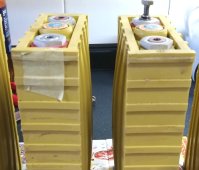
I see two primary challenges when providing compression. The first, is how to provide the correct total amount of compression. There are several posts that have calculated this to be around ~660 lbs for a 280Ah cell as well as a reliable way to get there (compressing a spring a certain distance). The other challenge is how to distribute or spread out that load such that is acts as somewhat uniform pressure on the face of the battery. This can be a lot more challenging and deceptively difficult to do. I have 1/2-1" wood, aluminum or plastic plates used to accomplish this but no real analysis justifying the selection of one thickness/material vs the other.
I'm an engineer and have access to some decent software tools to analyze these kinds of things so I decided to test one option I was considering.
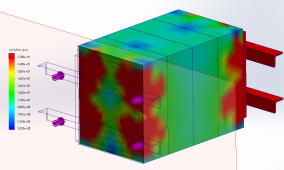
First analyzed design:
EVE304 cells
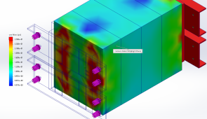
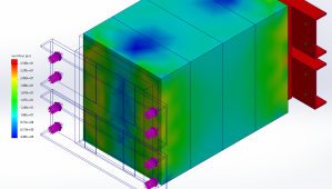
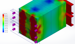
3/4" thick x 7" x 8" plywood spreader plates
1" x 1" x .125" angle iron beam
165 lbs applied at the washer contact surface area on the angle iron
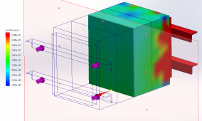
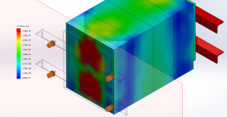
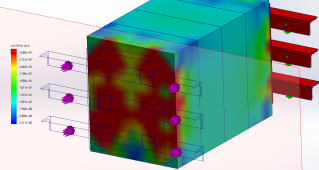
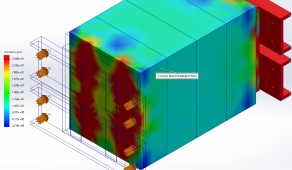
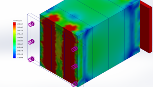
The two stress plots show stress at first cells surface and at the midplane (between cell 2 and 3). As you can see, there is very unequal stress at the first cell (peak loads exceed 50 psi) but it is very uniform at the middle (right at 12 psi).
Ideas for future iterations include
-using 1/2" aluminum plate instead of plywood
-using c channel instead of angle iron
-insert a shim between the angle iron and plywood at the center
I am most excited about the last one because it seems like a simple/easy fix to shift some of the load to the center of the pack and away from the corners where the angle iron goes over the edge of the plywood. Also, in my application I am limited to 13.5" in depth, so that allows for 13.5" - (4 x 72mm) = 2.16" (for both sides total) of length to figure out a way to spread the load.
I see two primary challenges when providing compression. The first, is how to provide the correct total amount of compression. There are several posts that have calculated this to be around ~660 lbs for a 280Ah cell as well as a reliable way to get there (compressing a spring a certain distance). The other challenge is how to distribute or spread out that load such that is acts as somewhat uniform pressure on the face of the battery. This can be a lot more challenging and deceptively difficult to do. I have 1/2-1" wood, aluminum or plastic plates used to accomplish this but no real analysis justifying the selection of one thickness/material vs the other.
I'm an engineer and have access to some decent software tools to analyze these kinds of things so I decided to test one option I was considering.
First analyzed design:
EVE304 cells
3/4" thick x 7" x 8" plywood spreader plates
1" x 1" x .125" angle iron beam
165 lbs applied at the washer contact surface area on the angle iron
The two stress plots show stress at first cells surface and at the midplane (between cell 2 and 3). As you can see, there is very unequal stress at the first cell (peak loads exceed 50 psi) but it is very uniform at the middle (right at 12 psi).
Ideas for future iterations include
-using 1/2" aluminum plate instead of plywood
-using c channel instead of angle iron
-insert a shim between the angle iron and plywood at the center
I am most excited about the last one because it seems like a simple/easy fix to shift some of the load to the center of the pack and away from the corners where the angle iron goes over the edge of the plywood. Also, in my application I am limited to 13.5" in depth, so that allows for 13.5" - (4 x 72mm) = 2.16" (for both sides total) of length to figure out a way to spread the load.