So I need a battery bank to run our stationary rv.
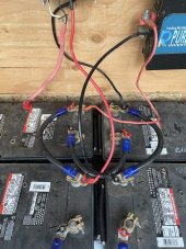
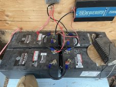
I bought four 170ah dekas. Got them from a reputable battery/solar dealer in Denver. The batteries seem to be good, he said they had 95% life left. Got them wired for 24v bank. Have a make sky blue 40amp controller.
Batteries hit 29v no problem, problem comes when about 10pm they are down in the 23.7 range( too low). I only need them to power the furnace fan and some led lights each night. My old batteries did this without a problem.
So I called the guy back up and told him batteries were not preforming well. He said he had no complaints on them and would switch them for another type if I wanted. He asked how I had them hooked up and I said the controller and inverter were coming off the battery 1 and 4 ( same terminals ). He said no the controller goes to battery 2 and 3 and the inverter goes to bats 1 and 4. I had never heard this.
This is what I want to figure out. What terminals exactly to come off of for the controller and inverter.
Thank you