diy solar

diy solar

Cooling FET based BMS?

HaldorEE

Solar Addict
Joined
Apr 20, 2020
Messages
1,633
I have read from several experienced users that it is wise to derate FET based BMS current ratings by 50%. I was wondering if anyone has any experience with adding cooling to a BMS that they would be willing to share? Does enhanced cooling capability increase the usable current rating of a FET based BMS or is there some other limiting factor that is going to kick in first (like the 6AWG wires that came on my "150A" Daly BMS).

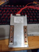
I just purchased this 300A Heltec BMS and its construction makes me think there is actually a prayer of it handling a reasonable fraction of its current rating (at least the cable connections provided hint this might be the case).
Heltec.jpg

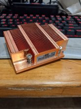
I bought two of these passive server CPU coolers for another project and ended up not using them. I should be able mount one or both (one on each side) on the Heltec BMS without difficulty. Once I get my 280 AH battery pack put together I plan on doing some experimentation to see how much difference in heat rise I get in the BMS with and without heatsinks. I really hope this Heltec BMS are not a disappointment. I don't see myself actually needing to draw 300A from the battery pack, but heat is the enemy to a long and happy life `when it comes to electronics.
Heat Sink.jpg
 
I have been pondering this approach as well (and actually have an identical CPU cooler to yours). At the very least it wouldn't hurt.

On another note, you may have noticed Daly recently introduced active cooling to their high current BMS lineup.
 
I have been pondering this approach as well (and actually have an identical CPU cooler to yours). At the very least it wouldn't hurt.

On another note, you may have noticed Daly recently introduced active cooling to their high current BMS lineup.
Too late for me unless I want to get rid of my current Daly BMS.

This is the same heat sink.


Miss read your message, you already have the heat sink.

I think as long as the fins are orientated up and down, that thing should be able to dissipate some heat.
 
  • Like
Reactions: Dzl
Too late for me unless I want to get rid of my current Daly BMS.

This is the same heat sink.


Miss read your message, you already have the heat sink.

I think as long as the fins are orientated up and down, that thing should be able to dissipate some heat.
One thing I found with this heatsink is that in the context of a CPU, it was MUCH more effective with some air flowing over it.
 
One thing I found with this heatsink is that in the context of a CPU, it was MUCH more effective with some air flowing over it.
True that.

Hopefully I won't need them, but if I do these look like they should mount right into the existing mounting holes of those heat sinks.


I love MPJA. I buy tons of surplus electronics from them.
 
  • Like
Reactions: Dzl
Cooling with added heat sinking is good. Issue is most of the BMS's have surface mounted MOSFET's soldered to PCB. Not really any good points to get a good thermal contact. Some BMS just snuggle heat sink again MOSFET plastic case which is not a great heat conduit. The BMS PCB also does not have great heat transfer.

The MOSFET main tabs are their drain connection. They are best heat transfer connection but they also have to be electrically isolated from the case or any heat sink. I have used some of the light blue adhesive heat sink pads. They are not super great for heat transfer but better then nothing and a lot better then the MOSFET plastic case. Check the coplanarity of all the MOSFET's and use thermal pads only as thick as necessary to account for non-coplanarity extremes. The thinner the pad thickness to get to copper or aluminum heat sink the better, within reason of not being so thin to easily punch through pad allowing drain of MOSFET to short to heat sink.
 
have read from several experienced users that it is wise to derate FET based BMS current ratings by 50%. I was wondering if anyone has any experience with adding cooling to a BMS that they would be willing to share? Does enhanced cooling capability increase the usable current rating of a FET based BMS or is there some other limiting factor that is going to kick in first (like the 6AWG wires that came on my "150A" Daly BMS).

I just purchased this 300A Heltec BMS and its construction makes me think there is actually a prayer of it handling a reasonable fraction of its current rating (at least the cable connections provided hint this might be the case).

There's a few key points: cooling obviously, max current of the mosfets, how well the current is shared between them.

Main problem for cooling is that they put the heatsinks on the package side of the mosfets (NB: it's plastic), in theory they should be cooled on the PCB side, where their thermal tabs are. Because of that the thermal resistance is around two orders of magnitude bigger than it should. Plus they use a really thick TIM as they can't avoid it because of variability in the soldering and the mosfets thickness, so that increase the thermal resistance quite a bit too. They compensate by putting a lot (like double...) of mosfets (I guess it's cheaper for them to do that than proper heatsinking) so there's less power per mosfet to dissipate.

Max current should be ok because of the large number of mosfets because of the cooling choices.

Current sharing really depends on the PCB design, if busbars are used (and how they contact the PCB, how thick they are, ...), where wires are connected, etc...


I bought two of these passive server CPU coolers for another project and ended up not using them.

They're not made for passive cooling. The fan isn't mounted on them but they require forced airflow to cool the CPU properly; the fans are mounted on the chassis which is used as a giant air duct (often there's proper air ducts made of plastic, mainly to be able to run the server open for maintenance without impacting the airflow). Now what you want to cool should give far less heat than a CPU so even if it's not an ideal heatsink it should be fine ;)

The problem is that the bottleneck is their heatsinking design, not what you can add on top. What I'd do is to heatsink the busbars where the wires are connected, they should have a better thermal coupling to the mosfets than the aluminium plates (but, again, it depends on a lot of things, the PCB design being the main one). Heatsinks with heatpipes (like the ones used on laptops) would be ideal to solve the very small available volume problem.

Another solution I never saw (yet) would be to remove the Al plates and immerse the whole BMS in mineral oil. It works well for things who are hard to heatsink due to their physical shape (like transformers for example) and some people did it with computers too. I'm pretty sure oil would cool the mosfets better than the Al plates but it's an educated guess, I didn't do the math so I may be wrong. If you then put the whole thing in an aluminium case you have plenty of surface area to dissipate the heat in the air. Of course the main problem to solve is oil leaking but that should be pretty easy with passthrough terminals for the high current wires and a passthrough connector for the small wires (if it works fine underwater equipment immersed 24/365 in the middle of the oceans it should be ok here too).


On another note, you may have noticed Daly recently introduced active cooling to their high current BMS lineup.

That's less then ideal. On something running 24/365 you want passive cooling as much as possible as fans running all the time will fail pretty quickly (even good quality ones) and when they fail the result can be catastrophic depending on the design of the thing (worst case is no fan speed and no temp monitoring: fan failure = device destruction + fire if unlucky).


Edit: ok apparently I completly missed @RCinFLA post so I wrote basically the same thing...
 
That's less then ideal. On something running 24/365 you want passive cooling as much as possible as fans running all the time will fail pretty quickly (even good quality ones) and when they fail the result can be catastrophic depending on the design of the thing (worst case is no fan speed and no temp monitoring: fan failure = device destruction + fire if unlucky).
This is an interesting point. Definitely a trade-off in reliability vs heat dissipation.

I have not owned either the passively cooled or actively cooled Daly, so I'm not sure if the actively cooled version uses the same heatsink as the older passively cooled BMS or not. If it does, the consequence of fan failure isn't so bad, but if the actively cooled version does use a smaller heatsink that would be a potential issue. I believe both have high temperature protection so ideally it would shut down the system before damage occurs, but who knows if that is true in practice, not an easy thing to test I imagine.

Daly has some of the highest current FET based BMS out there, there newer models advertise up to I think 500A. I suspect the turn towards active cooling is a result of them pushing (or exceeding) the limits of what a FET based BMS can/should do.

As to reliability. While I agree that passive is definitely more reliable, Inverters and other important components often use fans successfully enough.
 
I have not owned either the passively cooled or actively cooled Daly, so I'm not sure if the actively cooled version uses the same heatsink as the older passively cooled BMS or not. If it does, the consequence of fan failure isn't so bad, but if the actively cooled version does use a smaller heatsink that would be a potential issue. I believe both have high temperature protection so ideally it would shut down the system before damage occurs, but who knows if that is true in practice, not an easy thing to test I imagine.

Yes, in that case it should be ok. I was warning in more a general way (for example cheap chinese inverters might not be super safe if the fan fails).


Daly has some of the highest current FET based BMS out there, there newer models advertise up to I think 500A. I suspect the turn towards active cooling is a result of them pushing (or exceeding) the limits of what a FET based BMS can/should do.

You can switch multiple kA or more if you want, there isn't a magical limit (there's DC installations in the MW range and there's industrial machines using DC motors sucking many kA), especially as you're just switching it, not doing some PWM or other complicated things.

The problem is more an economical one than a technical one; a fan is really cheap compared to passive heatsinking ;)


As to reliability. While I agree that passive is definitely more reliable, Inverters and other important components often use fans successfully enough.

Yes, but it's very rare for them to run at max speed. They're also big fans running at lower rpm than smaller fans for the same airflow, so they have less wear on the bearings given the same amount of time.
 
Heat in FETs is going to be I^2R, and I bet you don't run 50% of max current that often.
A snap action thermostat bonded to part of the BMS could enable a DC fan, powered by the output side of the BMS. Could add capacitor or RC snubber if using an AC rated thermostat.
Running occasionally the DC fan should last a while. Kept cool the BMS should last longer.
You can buy low speed fans good for several years.

Alternatively, make a duct from the BMS to inverter's fan inlet, let that draw air.
 
Alternatively, make a duct from the BMS to inverter's fan inlet, let that draw air.
I really like that last idea. I am planning on an thermostat controlled exhaust fan for my electrical locker. I am building the electrical equipment into the galley module. Everything will be self contained in a single 8020 aluminum extrusion framework. The batteries will be on a ball bearing slide assembly to make them serviceable (and easily removable).
 
  • Like
Reactions: Dzl
Back
Top