diy solar

diy solar

Coulomb counter for DIY BMS

Cal

Solar Addict
Joined
Apr 28, 2020
Messages
752
I'm currently using a 300A Chargery BMS in my motor home. Unfortunately this BMS is woefully deficient in measuring current. Resolution is somewhere around 1A. This results in the Chargery SOC gauge being totally unreliable. The gauge displays >90% SOC when in reality the battery is below 50%.

My objective is to design/build/test a coulomb counter with current resolution in the tens of mA.

I'm using an AD623 Instrumentation Amp to amplify the shunt signal with a gain of 2. This amp is extremely nice as it operates with an input 0.3V below-ground-signal. This is important as the shunt voltage can go negative 75 mV @ -300A.
AD623

The output of the amp goes into an ADS1116 (16-bit A/D). The A/D is scaled (by Arduino) for 0.256 V full scale. That means the full current range of 600A (+/-300A) is compacted into a 0 to 256 mV scale. Zero current is set to 256 mV / 2 = 128 mV. A reference voltage of 128 mV is injected into the amp to provide an output offset voltage of 128 mV when shunt current is zero. Current resolution is about 16 mA/bit.

The 128 mV reference voltage is derived from an AD780 2.5V voltage reference and a voltage divider consisting of 18.46k and 1 k resistors. 18.46 kohm is derived from paralleling 20k and 240k. This voltage doesn't need to be exact as voltage offset and amp gain are corrected in the Arduino sketch.
ADS1115.jpg

I've connected the circuit to the Chargery 300A shunt for initial measurements. The connection has no effect on Chargery current measurements. Both circuits can operate independently.

The SCL / SDA signals are connected to the I2C bus of an Arduino Uno. In addition, the Uno is mechanized as a data logger. Measurements are taken every second and stored on a SD memory card.

Here's some initial test data.

I_shunt1.jpg
I_shunt1.jpg

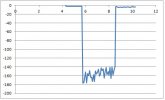
During the first 350 seconds a solar charge of 3A is turned on and off. Around 370 seconds the 2500W inverter is turned on. A -100A spike is seen as inverter caps are charged. Around 400 seconds the microwave is turned on, with current of -160A.

I_shunt2.jpg
I_shunt2.jpg

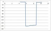
This graph shows about 20A of inverter ripple current. I got some 100 mH inductors and 100 uF caps on order to add a LC filter to the input of the amp. Not sure why the current has a decreasing slope. More testing/evaluation to follow.
 
Definitely going going to follow your progress.

I am happy with the Chargery in regard to most things, but the current and SOC tracking is definitely a short fall.
 
Very nice ;)

I'm using an AD623 Instrumentation Amp to amplify the shunt signal with a gain of 2. This amp is extremely nice as it operates with an input 0.3V below-ground-signal. This is important as the shunt voltage can go negative 75 mV @ -300A.
AD623

According to the datasheet it's not 0.3 V but 0.15 V which doesn't change much here though; the main problem is that even if the input can go below -Vs I'm pretty sure it can't amplify that.

Also it has a 0.35 mV max Vos which translates to a 1.4 A max offset so be careful about that ;)

Not sure why the current has a decreasing slope.

Probably because of the transformer and/or magnetron heating up.
 
According to the datasheet it's not 0.3 V but 0.15 V which doesn't change much here though; the main problem is that even if the input can go below -Vs I'm pretty sure it can't amplify that.

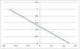
I bench tested the AD623. With a gain of 2 and reference voltage = 0.485V, max negative input voltage applied was 0.25V. A gain of 2 remained throughout the entire negative input voltage region. x-axis is input voltage, y-axis is output. At 0V input, output = 0.485V
Though not visible, there are 20 data measurements.

AD623IN_OUT.jpg
 
Nice to see it can do that ?

Linearity isn't the best at the zero crossing but that's to be expected I guess.
 
Installed the 100 uF ceramic cap and the 100 mH inductor (thanks to BiduleOhm for finding the components). The low pass filter is inserted between the AD623 output and ADC input. The filter creates a dramatic reduction in ripple current when the microwave is operational. I can live with that performance.

I_shuntFiltered.jpg

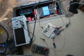
Here's a photo of my setup in the motor home. The 180 AH LiFePO4 battery is located in a compartment under the entry stairs. The top of the battery is covered with cardboard. Laying on top of the cardboard is the bluish Chargery BMS.

P1001468R.jpg

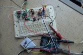
A more detailed view of the circuit. To the far left is the AD780 voltage reference, then comes the AD623, then the low pass filter, and at the right end is the ADC. The neighboring small white board has a push button switch to halt data acquisition. Not seen is the SD card reader.

P1001469R.jpg


Edit, current resolution is 31 mA/bit. 16 mA/bit is not correct.
 
Last edited:
Running into some problems. I want to compare my newly constructed Arduino Uno current logger against the Chargery RS232 streaming data. An Arduino Mega data logger is connected to the Chargery RS232 port via a RS232-to-TTL module. As soon as the connection is made, the current logger output changes from -0.2 A to -0.7 A. An offset is injected into the current measurement.

Both Arduinos are powered from a dc/dc converter adjusted to 7V. The dc/dc converter gets its power from the battery under test. In other words, both Arduinos are connected to battery ground. The RS232 ground wire however has a potential of 342 mV above battery ground. When the RS232 is connected to Arduino, the two grounds are tied together. The 342 mV is shorted out. I don't know what that does to the Chargery BMS. Connecting the ground RS232 wire to Arduino causes the other Arduino current measurement to change from -0.2A to -0.7A.

This has no effect on Chargery current measurements as currents below 1A are registered as 0A.

P1001470R.jpg
 
What happens if you connect the RS232 ground through a few kOhm resistor?
 
  • Love
Reactions: Cal
Very good! Installed 1.1 k ohm between Chargery RS232 ground and RS232-to-TTL ground. That knocked out the offset error. Both units appear to measure correctly.
 
Well obviously it's a ugly patch but if it works... :D

Just watch out for com errors on the RS232 link. 0.3 V shouldn't matter much but you never know (especially as something isn't quite right to begin with) ;)
 
First thing that has to happen off of the shunt is a very low frequency corner frequency filter to convert the 120 Hz ripple to average value. Average is used (in contrast to rms value) to represent average current to battery which better represents AH's discharged or charged.

It can be done digitally with about 1.2 ksps on ADC and averaging oversamples in software.

Many battery monitors use just an R-C filter with couple Hz's corner freq. Because this generally uses a large value cap some cheapo's are using electrolytic caps which I don't recommend due to leakage that gets worse with age. Don't recommend using L-C as will likely have ringing.

Make sure your op amp input common mode can run down to ground if you are not using a negative supply on op amp. Op amp output cannot likely run to ground so there will need to be an offset.
 
Last edited:
First thing that has to happen off of the shunt is a very low frequency corner frequency filter to convert the 120 Hz ripple to average value. Average is used (in contrast to rms value) to represent average current to battery which better represents AH's discharged or charged.

You may have missed post 7: the inclusion of a LC filter (100 mH & 100 uF ceramic). The filter significantly reduces the 120 Hz, 20App ripple. I don't expect there will be any ringing. There's no drastic switching, which is the source of ringing.

I'm using a single supply for the op amp (AD623). The current shunt max signal is 75 mV below ground. I've tested the op amp to 0.25V below ground with no error in amplification. Reference post 5.
 
Got the two data loggers operating. Data is recorded every 5 seconds. During most of the logging session the current was around -0.8A (quiescent load current) of the motor home. My DIY current meter recorded the correct values while Chargery recorded 0 A. This is a real problem. Chargery looses at least 10 AH per day in the coulomb count. WH, AH and SOC readings can be way off. Chargery gets back on track only if the battery gets fully charged. It then switches to the maximum battery AH or WH value located in the setup.

Here's a section of the data logging where the microwave is on. The Chargery current ripple is about 20App (or higher), while the DIY meter had no ripple. Chargery needs a low pass filter (besides better current resolution).
ChargeryLogger.jpg

ShuntLogger.jpg
 
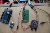
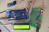
Added a LCD display to get immediate current feedback. Also swapped Auduino Uno for a Mega. It's simpler to plug in all the wires when using a Mega.

There is a thermal problem. The offset voltage drifts with temperature. Heating up the circuit with a hair dryer (from 18C to ~40C) increases current display from -0.75A to -2.00A. Still need to isolate the problem part. This may get beyond my project commitment level.

Edit, most likely the thermal issue is with the instrumentation amp AD623.

P1001471R.jpg

I contacted Jason (Chargery) regarding the 330 mV difference between the BMS serial data ground and battery ground. He states the RS232 ground is also the internal BMS ground. That means you can not directly power the data logger from the BMS battery. That's an important fact and would be nice if that is mentioned in their documentation. He suggested inserting a diode in series with the dc/dc converter ground lead to the battery. I asked him about the alternative of adding a resistor to the RS232 ground, but he didn't reply.
 
Last edited:
There is a thermal problem. The offset voltage drifts with temperature. Heating up the circuit with a hair dryer (from 18C to ~40C) increases current display from -0.75A to -2.00A. Still need to isolate the problem part. This may get beyond my project commitment level.

Probably the amplifier part of the circuit. maybe not the op-amp itself but Rg? I don't know how much its tempco affects the final accuracy but that would be the first thing I'd check ;)

If it's the op-amp or ADC then you just have to hope the error is linear with the temp so you can compensate most of it in software easily (as long as you have the temp available too).

I contacted Jason (Chargery) regarding the 330 mV difference between the BMS serial data ground and battery ground. He states the RS232 ground is also the internal BMS ground. That means you can not directly power the data logger from the BMS battery. That's an important fact and would be nice if that is mentioned in their documentation. He suggested inserting a diode in series with the dc/dc converter ground lead to the battery. I asked him about the alternative of adding a resistor to the RS232 ground, but he didn't reply.

But the BMS internal ground is connected to B- unless I missed something, no?

Yeah a diode to shift the ground works too, but be careful if you use 5 V logic as most components don't tolerate more than 5 or 10 % under the nominal for the PS voltage.
 
But the BMS internal ground is connected to B- unless I missed something, no?

That's the problem. BMS internal ground (or RS232 ground) is not directly connected to B-. It's 330 mV above B-. I'm messing with the BMS electronics in an unknown way when connecting the two together.
 
Ah ok. That's really weird; I really wonder where does this voltage comes from...

With a few k resistor you don't risk doing harm to the electronics, at worst you'll have corrupted data because of the high impedance ground but that's all ;)
 
The thermal error appears to only affect the offset, not gain. I increased the load by 10 A and the display increased by 10A. The gain is OK.
Back in the "old days" I would have a can of cold spray that can be applied to individual parts. Now I'm limited to a bag of frozen peas. Ha Ha.
So the game plan is to constantly measure AD623 temperature to apply a software offset correction. Or a different amp?

Having access to my old work lab Thermotron temperature chamber would be very nice right now.

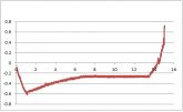
Here's a plot of night time current. On the left side the sun is dropping and current goes negative. On the right side of the plot the sun is rising and current goes positive. The night time quiescent load should be -0.7A. Ambient temps drop and the current gets more positive (from -0.6A) until it levels out just past the 6 hour mark (to about -0.25A).

AD623thermalEffect.jpg
 
Offset is even easier to compensate for ;)

Yep, measure the temp and correct the offset in software. Something like final_value = (raw_value * gain) + offset + temperature_correction;

Well, you probably have a fridge, a freezer and an oven so you can do some tests even if it's not really precise of course. Just don't use a microwave oven... ?
 
Back
Top