I also put in dual pole breakers on the incoming PV wire. It was a recommended method by the folks that reviewed my design. It turned out to be a good solution for space savings in my compartment. Mounting breakers on a DIN rail on the wall left space on the floor for other devices.
You are using an out of date browser. It may not display this or other websites correctly.
You should upgrade or use an alternative browser.
You should upgrade or use an alternative browser.
Crude at this point, but my design needs scrutiny please
- Thread starter Stepandwolf
- Start date
Stepandwolf
Solar Enthusiast
- Joined
- Nov 14, 2020
- Messages
- 668
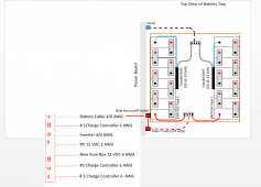
I have a 4-breaker box that is made for outside although I am using it inside. My idea was it kept the breakers from being accidentally bumped. I have one string now with two breakers, and will add another string of panels and they will have their own breakers and SCC.I also put in dual pole breakers on the incoming PV wire. It was a recommended method by the folks that reviewed my design. It turned out to be a good solution for space savings in my compartment. Mounting breakers on a DIN rail on the wall left space on the floor for other devices.
Stepandwolf
Solar Enthusiast
- Joined
- Nov 14, 2020
- Messages
- 668
Just had a laugh.....Will just released a video with his Tesla charging system that runs dual inverters. Guess what fuses he chose for his inverters, 300A Class T, and in fact, the exact same brand I have. If you look back in this message string, I think that is where a user here made the Class T suggestion. On his own website he has the ANL fuses listed, but hasn't put the Class T there for some reason.
Stepandwolf
Solar Enthusiast
- Joined
- Nov 14, 2020
- Messages
- 668
100 Proof
"Please Lord, don't let me do something stupid."
- Joined
- Feb 14, 2021
- Messages
- 206
In my opinion, the negative side of the charge controller and the 24 to 12 converter are still wired to the wrong side of your shunt.
If you don't care about measuring anything except the outflow to your inverter, then maybe it's fine. But there's no way you're going to get accurate information about battery state of charge the way it's wired.
If you don't care about measuring anything except the outflow to your inverter, then maybe it's fine. But there's no way you're going to get accurate information about battery state of charge the way it's wired.
chrisski
Solar Boondocker
- Joined
- Aug 14, 2020
- Messages
- 5,192
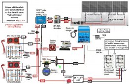
To get the shunt in the correct place and the battery cutoff switch, You'll need to join the two batteries with a busbar, and on the positive side between the two busbars, place the Class T fuse followed by the on off switch; on the negative side between the two busbars add the shunt. This is how I will wire mine:

What that diagram does not show is after the shunt, the negative wires go to a positive busbar identical to the first. The positive line labeled RV 12 VDC is actually 24 VDC to a converter.

What that diagram does not show is after the shunt, the negative wires go to a positive busbar identical to the first. The positive line labeled RV 12 VDC is actually 24 VDC to a converter.
Stepandwolf
Solar Enthusiast
- Joined
- Nov 14, 2020
- Messages
- 668
Seems based on my Victron sample I am using, you are right, and I really appreciate your persistance. In the Victron diagram they don't have a converter so I just "threw it in". ThanksIn my opinion, the negative side of the charge controller and the 24 to 12 converter are still wired to the wrong side of your shunt.
If you don't care about measuring anything except the outflow to your inverter, then maybe it's fine. But there's no way you're going to get accurate information about battery state of charge the way it's wired.

curiouscarbon
Science Penguin
- Joined
- Jun 29, 2020
- Messages
- 3,024
Nice! The shunt should observe all the solar charge and 24->12v converter discharge and inverter discharge current in the configuration shown in your most recent post.
Stepandwolf
Solar Enthusiast
- Joined
- Nov 14, 2020
- Messages
- 668
Please compare my latest diagram with the attached Victron diagram. I am failing to see how my bus>switch>fuse>inverter is different than what they did?To get the shunt in the correct place and the battery cutoff switch, You'll need to join the two batteries with a busbar, and on the positive side between the two busbars, place the Class T fuse followed by the on off switch; on the negative side between the two busbars add the shunt. This is how I will wire mine:
All of you guys are gurus and I am the newbie, so I really appreciate all the kicks in the butt.
Attachments
curiouscarbon
Science Penguin
- Joined
- Jun 29, 2020
- Messages
- 3,024
Haha just I'm an amateur who is trying to build a strong DIY LFP Solar Energy Storage System without burning my house down or hurting myself LOL
At first I was like "Oh I'll just buy an off the shelf LFP Battery" *looks at prices* oh god, engineering time.
*more than a year later* still reading about the technology and just beginning to feel confident enough to assemble 8S pack like you're building. gonna use the multiplus 24/3000 and bluesolar mppt as well (yours seems to be smartsolar which just has bluetooth built in. lol so weird how the bluesolar one has no bluetooth... anyways..)
I might have missed part of the battery fuse discussion;
do you have any feelings on ANL fuse vs MRBF fuse?
Asking because noticed you have 8S 280Ah EVE cells which are capable of easily delivering over 1000 Amperes flow in event of short circuit.
The datasheets for a couple of MEGA/ANL fuses I downloaded just now indicated 800-1000A interrupt rating. Which means, if the 8S EVE pack delivers more than that amps rating, it has an elevated chance of forming a plasma arc that replaces the fuse with a hot plasma conductor. At 24VDC the arc potential should be tempered relative to 48VDC.
Anyways. I checked out an Eaton MRBF fuse datasheet just now and it said interrupt rating 5000A @ 32V DC.
(not saying which one is best for your case, but mentioning it because fuse interrupt ampere rating is a major popular topic of discussion because there's some uncertainty still about what interrupt rating is needed for a given LiFePO4 battery pack.)
For my 100Ah 8S packs, I'll be using MRBF fuses mounted on the positive terminal of my pack. And I'm still hoping that I didn't skimp out on interrupt rating.
The Fuse I got is Blue Sea Systems Terminal Fuse, and it has 5000 Ampere Interrupt Rating. https://www.bluesea.com/products/5190/MRBF_Terminal_Fuse_-_300A this one is 300A and might be a candidate substitute for the 300A ANL fuses currently specified on the diagram.
I also just noticed that the negative wire is significantly thinner than the 2/0 incoming positive, so maybe my concerns about interrupt rating are overblown.
chrisski
Solar Boondocker
- Joined
- Aug 14, 2020
- Messages
- 5,192
You set it up like Victron had in the diagram. I’m used to one Master off from the battery, but you have two. A circuit breaker and battery switch. THere is a third breaker feeding the converter. If that is not a self restting breaker than that’s fine. If it is, there’s no way to shut the battery off from the converter without undoing a cable.Please compare my latest diagram with the attached Victron diagram. I am failing to see how my bus>switch>fuse>inverter is different than what they did?
For the shunt, placement is fine. I don’t like the idea of connecting multiple big lugs to one stud. Sometimes its not physically possible. If the 712 says in the specs you can connect two lugs there, then its fine, but I would still join the two negatives with a busbar prior to the 712.
Stepandwolf
Solar Enthusiast
- Joined
- Nov 14, 2020
- Messages
- 668
I see now that by adding the converter to the busbar, that there are 5 items connected. I could probably get away with putting the SCC and converter cable together, or T the bats then into the busbar. Whatever saves my trailer. ThanksYou set it up like Victron had in the diagram. I’m used to one Master off from the battery, but you have two. A circuit breaker and battery switch. THere is a third breaker feeding the converter. If that is not a self restting breaker than that’s fine. If it is, there’s no way to shut the battery off from the converter without undoing a cable.
For the shunt, placement is fine. I don’t like the idea of connecting multiple big lugs to one stud. Sometimes its not physically possible. If the 712 says in the specs you can connect two lugs there, then its fine, but I would still join the two negatives with a busbar prior to the 712.
Stepandwolf
Solar Enthusiast
- Joined
- Nov 14, 2020
- Messages
- 668
One other person I ran into on here was going to use one of those busbars with multiple MRBF on it. When I researched it, I found a reason not to go that way. I wish I could find an excellent chart I had found that shows what to use where and when. That same chart further supported the use of Class T before the inverter.I might have missed part of the battery fuse discussion;
do you have any feelings on ANL fuse vs MRBF fuse?
As indicated by the *, the "smaller" gauge wires on the ones coming off of the BMS. So yes, "my" wiring, where I could choose gauge, is all proper. But the 2 and 6 ga on the BMS's are small from my calculation, but Daly insists they are fine and I don't know of anyone who changed them as it would be a PITA.I also just noticed that the negative wire is significantly thinner than the 2/0 incoming positive, so maybe my concerns about interrupt rating are overblown.
The Victron shunt should have enough threads on the bolt that two lugs (one from each battery) will fit. That's how I did mine. I'm not seeing enough difference in amp draw through each BMS that would lead me to believe that stacking two lugs will throw off the balance between the batteries. Joining the two battery cables with a bus bar or something similar may be a better way to fine tune the balance. But like I said, it's looking good on my system.
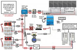
The revised diagram (version M) looks good.
The revised diagram (version M) looks good.
Stepandwolf
Solar Enthusiast
- Joined
- Nov 14, 2020
- Messages
- 668
We aren't talking about the negative sideThe Victron shunt should have enough threads on the bolt that two lugs (one from each battery) will fit. That's how I did mine. I'm not seeing enough difference in amp draw through each BMS that would lead me to believe that stacking two lugs will throw off the balance between the batteries. Joining the two battery cables with a bus bar or something similar may be a better way to fine tune the balance. But like I said, it's looking good on my system.
The revised diagram (version M) looks good.
We aren't talking about the negative sideThe positive side has four connection points and five wires going to it. Three are 2/0, but one is 6ga and one is 10ga which I think would be fine on a common connector.
Yes, I know. I was letting you know that joining the batteries at the shunt is possible. It isn't necessary to join the battery negative cables with a bus bar and then run cable from the bus bar to the shunt.
Stepandwolf
Solar Enthusiast
- Joined
- Nov 14, 2020
- Messages
- 668
Actually, if you look at my last version, it shows the two negative cables going from the BMS to the shunt as you suggested. In the last change to the drawing, the bus bar was moved to the other side of the shunt such that only the battery negative goes into the shunt and I will put both connectors on the rather large shunt bolt.Yes, I know. I was letting you know that joining the batteries at the shunt is possible. It isn't necessary to join the battery negative cables with a bus bar and then run cable from the bus bar to the shunt.
Similar threads
- Replies
- 50
- Views
- 3K
- Replies
- 7
- Views
- 564
- Replies
- 3
- Views
- 275


