diy solar

diy solar

CTs Vs. Toroids

svetz

Works in theory! Practice? That's something else
Joined
Sep 20, 2019
Messages
7,497
Location
Key Largo
What's the difference between the two (other than price, Toroids are around $0.30/each)?

Current-Probes-1-300x163.png
magnetic-field-in-a-toroid-core.jpg

Curious if they can be used as a poor-man's CT for simple projects not requiring high-accuracy, they seem to be about 50x less expensive.
 
Last edited:
Most CT transformers are toroid because toroid cores have less stray leakage inductance.

The openable C-clamp toroid cores are convenient but the break in the core does not have a perfect mechanical tolerance closed re-fit so there will be some increased leakage inductance greater than a continuous circular core.

Leakage inductance can allow some stray pickup from other wires around the CT primary sensing wire that can corrupt the desired reading a bit.

Shunt resistors are best accuracy but having electrical isolation is important in many cases.

The best accuracy CT sensor is a closed loop hall effect sensor. This is not what you find on Amazon or Alibaba. They are open loop type. Closed loop have a hall effect sensor embedded in core and a field cancelling coil driven by a moderate power op amp. The 'closed loop' part is the op amp drives a counter field to nearly cancel out the field in the core. This keeps the core very linear with little magnetic net core field. They are very accurate from low level to high level of current. Downside is the op amp requires a separate DC power supply. You can get these with 300 kHz to 500 kHz bandwidth.
 
Last edited:
I suspect that they are the same technically...but to be accurate the CT has
to have a lot more windings (see image) as it operates like a transformer
and the thru wire is a single winding so the CT needs more to compensate.

But hoping someone knows for sure, or even better the equations for CT
voltage to windings/amps.

I get Turns(primary) / Turns (secondary) = Voltage (Primary) / Voltage (secondary),
But not sure how that got to current in the primary.
Vector-300x233.webp
 
Last edited:
Voltage from the transformer equation above seems weird.

A toroid with 20 windings acting as a CT measuring 5 amps on 120 volts AC line would be: Vsecondary = Vprimary * Turnssecondary / Turnsprimary, or
120 X 20 / 1 = 2400V? If there were 100 windings, the voltage would 12,000V?

That's a lot of voltage. Possibly no meaningful current??

Wikipedia says:
CTs are specified by their current ratio from primary to secondary. The rated secondary current is normally standardized at 1 or 5 amperes. For example, a 4000:5 CT secondary winding will supply an output current of 5 amperes when the primary winding current is 4000 amperes.
If the voltage/windings is correct then via Ohms law I guess that makes sense. So, in our example that 5 amps @ 20:1 windings that would be 5/20=.25 amps?

That seems crazy though. Two wires running in parallel would have a winding of 1, so the second wire would have the same voltage and amps? That's not what I see in real life (I will see ghost voltage in the second wire if the primary has enough current in it). Missing something here....
 
Hmmm, let's say the wikipedia part is correct about the current, and all those windings have 2Ω resistance. Then the voltage on the CT in the example above at .25 amps would be V=IR, V=0.25 x 2 = 0.5V. If there were 100 windings, then 5/100 = .05 and with 20Ω resistance V=1?

We know looping the primary through the CT affects it, it's how you can use a 30 amp CT to measure a 10 amp circuit (by using 3 turns to triple the current measurement). Shown below, a 300/5 CT can be converter to 100/5 with three loops:

transformer-trans55a.gif

So with 1 loop @ 30 amps with 20Ω resistance in the CT the secondary current would be 30 x 5 / 300 = 0.5 amps and 10V. 10 amps with 3 loops would be 10 * 5 / 100 = 0.5 amps, and 10V.

Hmmm, let's say the CT does act like a step-up transformer via transformer equation Vs=Vp*Ns/Np, then the voltage gets very high. But, that might be the ideal voltage and not possible because there is resistance. So, both are right, but you need to factor resistance in?
 
Last edited:
It is a standard transformer, just with a high turn's ratio, like 1 turn primary to 1000 turns secondary. Problem is the 1000 turns secondary is fine gauge wire and has a lot of wire resistance, series inductance, and stray inter-layer capacitance. This effects the voltage delivered to burden load resistor. They will typically throw some extra secondary turns to make up for secondary losses, but this makes it very particular to external burden resistance value used.

On first level, the secondary winding resistance creates a voltage dividers with burden resistor. More involved is effect of load capacitance and series inductance effects. If the burden resistance is too large it allows earlier onset of core saturation limiting the maximum amount of primary side current.

It is common to use a 100-ohm burden resistor since that is very close to the characteristic impedance of a twisted pair of wires as a transmission line.

Core must be large enough to take primary current without getting too close to core saturation.

You are still dealing with a high permeability core for 50/60 Hz sensing which has a non-linear 'S' hysteresis B-H curve making the output vary 10-15% over low to highest current range.

Attached spec sheet gives some insight on the effects.
 

Attachments

  • CT transform Talema AC 1010.pdf
    344.4 KB · Views: 4
  • CT transform Talema AC.pdf
    341.2 KB · Views: 5
Let's see what we can figure out from the spec sheet @RCinFLA
linked for a CT rated for 10 amps that has 1,000 windings.

From the chart to the right, at 10 amps & 100Ω it's 1V.

Using the Is = Ip * Ns / Np formula we'd have
Is = 10 * 1/1000, so Is = 0.01.

V=IR, so V=0.01 x 100 = 1 ✅

So, it does appear to follow the transformer winding rule.
1673785877260.png
 
So, from AliExpress you can get a (knock-off?) AC1010 CTs for <$3 and from Digikey for less than $6. Sounds like the way to go.

But... would a 36-winding toroid like a VTCB921 with a 100µh inductance work?
At 10 amps, using the Is = Ip * Ns / Np then Is = 0.28 amps. To get a 3V range you'd need a 11Ω resistor.

Doubtful that it will work due to the inductance at 60 Hz, but not sure how you'd calculate the impact. The CT datasheets say what frequencies they work at, but not how much inductance they have. Inductance changes with increasing frequency (usually dropping to zero at high enough frequencies), but 60 Hz is pretty low.

Let's see if we can figure that out... inductance is defined as:

L = μN²A/l
  1. L = Inductance (H),
  2. μ = Permeability (Wb/Am),
  3. N = The coil's number of turns,
  4. A = The coil's cross sectional area,
  5. l = Length of coil (m).

Let's assume μ and A are roughly similar between similar sized torids and CTs. We can then say c = μA, and calculate L assuming an l of 1 cm per winding. For 36 windings of the VTCB921 that simplifies to: 100 = c 36² / .36, or c = 100 / .36. Then reusing c, for the 1000 windings the CT would have we get an inductance of 100/.36 * 1000² / 1000 = 277,778 relative, or 2800x greater. While A would be difficult to change, the inductance could be varied based on μ. That is to say, I'm still pretty clueless but at least suspect CTs have fairly high inductance.
 
Last edited:
The core material and operating frequency make a HUGE difference.

A toroid is not just a toroid (judged by size alone) or even by just the number of turns.
You need to specify the correct CT for the correct application.
There are conflicting requirements, so in order to get something you must have, you may also need to sacrifice something else that is less important for your particular application.

Generally, current transformers fall into two very broad classes based on the intended application.
Low frequency 50/60Hz applications for very precise and linear low frequency measurement for instrumentation.
High frequency applications that need to have a very fast rise time, usually used for current limiting application, where accuracy is secondary to sheer speed of response. Typically used within switching power supplies.

There are two limiting factors that complicate the whole thing, core saturation, and self resonance.
Any transformer stops working above self resonance, the windings must be inductive not capacitive at the operating frequency !
What works really well at 50/60Hz is not likely to work well, or at all at tens of Khz. And the reverse is true too.
And a current transformer needs to have a very high inductive reactance at the operating frequency and remain well below self resonance.

A lot of the cheap Chinese current transformers are very poorly specified, and really need to be tested to find out what you have actually bought.
The cheapies can work very well indeed, if you are prepared to test a few samples from different suppliers.
So what are you actually trying to do ?
 
Last edited:
For a CT your measuring the AC current in the cable, it does not matter if the cable is connected to 380V or 10V, it's the current thats important. so simply use the turns ratio, the maximum current in the primary and the burden resistor value.

Ratio = 200:1
Burden resistor = 50R
Primary max current = 100A
Given 1 turn on the primary then

100A/200 = 0.5A
V=RI = 0.5*50 = 25V
25VAC RMS across the resistor at 100A primary current.
 
Understand the physics & math.

Core behavior differs with material and treatment, for instance annealing and direction of magnetic field, if any, during annealing.
Some sites go into the details and applications.

There is a link in the following post on inductors in LTSpice.
It shows how to generate a BH curve and built a "Chan" model.
The hysteresis and other characteristics will affect how well current from one wire is coupled into the other.


I think you may find the Wurth WE-TPBHV have nice characteristics of tightly coupling windings at line frequencies. (don't assume just the frequency response in data sheet.)

 
Understand the physics & math.
The math is pretty simple, its just a transformer.
The trick though, is to stay within certain operating parameters and limitations.
Lets deal with the very easy ones first to get them out of the way.

The current rating has nothing to do with the core, only temperature rise in the secondary winding.
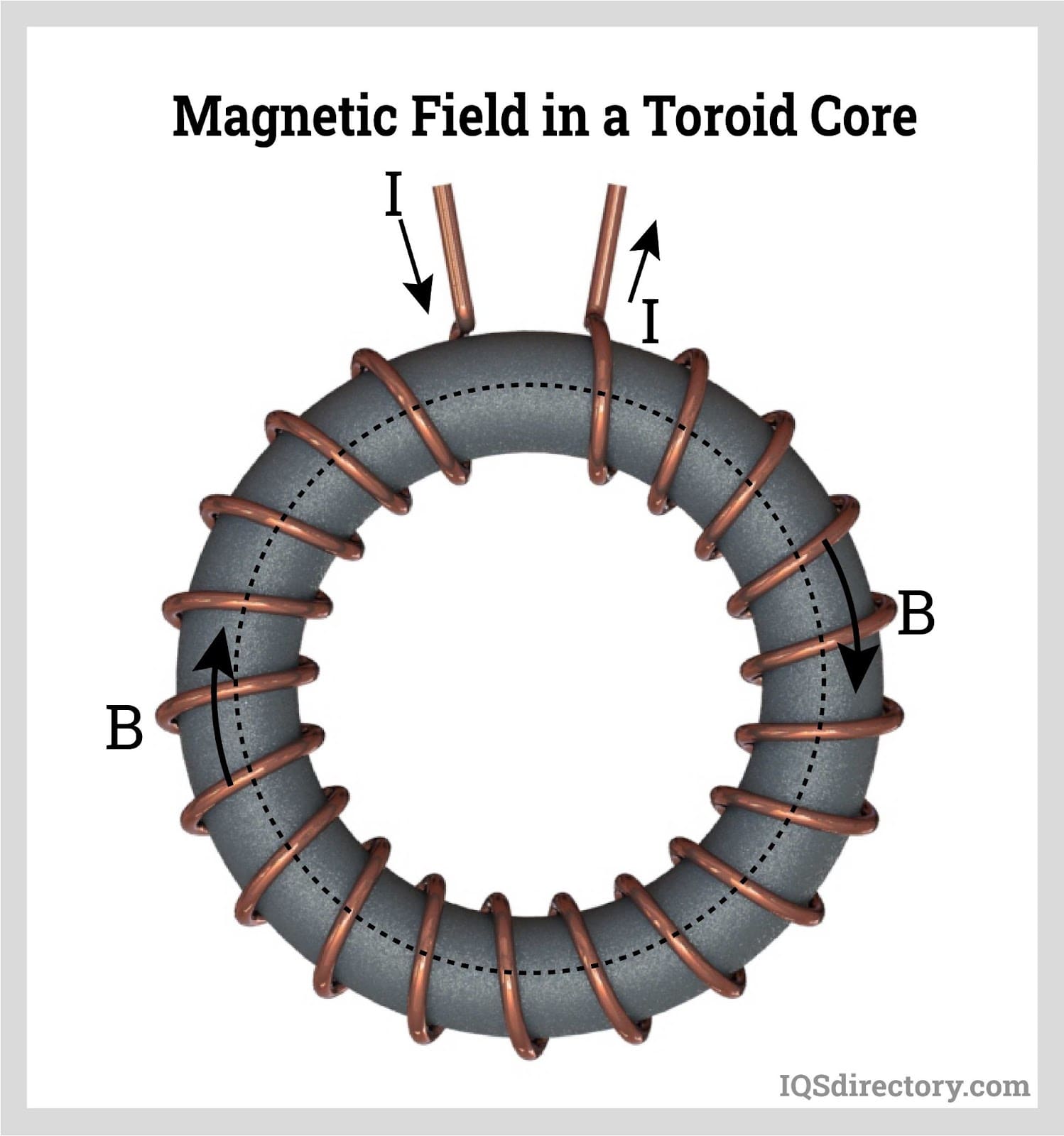
The flux swing in the core depends upon the turns, the frequency, and the cross sectional area (Faraday's Law)
And of course the turns ratio. All this is no different to designing an ordinary garden variety voltage/power transformer.

Now the tricky bits.
We want it to be small, because its not transferring much power. But a small core cross sectional area, requires a lot of turns, especially at very low frequencies. So we arrange things so it has say 1,000 turns and saturates at a few volts with that combination of turns and core cross section.

Now we want the inductance to be high enough so that the magnetizing current is very low compared to the current we are measuring.
Easy, we use a very high permeability core that has high inductance per turn. Usually some kind of very thin metal foil wound into a toroid shape.
This can be silicon steel, mumetal, or amorphous nanocrystaline material.

So far so good. It works fine at 50/60Hz, but the very high inductance and large number of turns creates a self resonance at a very few kHz.

Oh,dear, we want to measure current at 30 kHz, so this will not work. So try again with less turns, and a lower loss core such as very high permeability ferrite. So we use a different core and only 100 turns and we lift the self resonant frequency to 200 Khz. But our 100 turns does not produce much inductance, even with a largish toroid, and our magnetizing current at 30 Khz is going to effect linearity, but we do not care.
We sacrifice some accuracy for something that works at a much higher frequency.

Now if you do the maths, you will find that Faraday's law and the self resonance problem FORCES you to use a high permiability core material with a low loss material, so you need to be a bit choosy about what core you use, and its size.

Faraday's law is also very limiting on secondary voltage. If you need a lot of secondary volts, you need a larger core cross section and more turns.
Big difference in designing a CT that will produce 100mV across a burden resistor, and one that will produce 5v across a different burden resistor.

The maths is pretty straightforward, the trick is designing something where all the numbers end up being reasonable. That requires some insight and a few compromises.
 
Another way to think about all this, just imagine you are building a conventional transformer, and the CT secondary is the "transformer primary", of this new transformer you are designing, being energized at say 100mV and 50/60Hz. Easy, until you start to realize how small the cross sectional area of the core you would like to use.

Also, this winding needs to have a low inductive idling current or at least something very low compared to the design maximum full load current which might be 100mA for example. That places even more stringent demands on the core. It must have a very high flux swing capacity and a very high permeability unless its going to be super large in size.
 
The math is pretty simple...
Oh good! AFAIK, from the physics they are the same device, they're just sold for different purposes as they have different characteristics (i.e., windings & magnetic permeability of the core material). That's what made me wonder if a toroid could be used as CT.

Perhaps with math you could provide an example that would demonstrate calculated voltages of a VTCB921 toroid at 60 Hz and at what frequency the inductance falls off when used as a CT (36 windings, 100µh inductance)? As you can see from the prior posts the transformer calculations (e.g., Is = Ip * Ns / Np) looked like the easy part.

There is a link in the following post on inductors in LTSpice.
Interesting you brought up spice, I did try modeling it with the "simple" circuits calculator... but ran into the problem that it became clear I didn't know what I was doing with the inductance (was it in series as shown below, or the inductance of the transformer?).

The left side of the transformer is 120V@60 Hz running 10 amps (what you might expect a CT to be measuring). 1:36 on the windings to simulate a VTCB921. Then I put in a voltage splitter to get a < 2V sample port with high enough overall resistance to drop the total current flow to under 150 mA (e.g., suitable for an ADC). The right size uses the toroid's inductance for the transformer inductance.

4H transformer with Toroid inductance in seriesUsing Toroid inductance for Transformer inductance
1674306013117.png1674308255000.png

From the simulation, both circuits work. So, neither solution really leads me to any insights as to if or how well a Toroid would work compared to a CT. Similarly, changing the frequency just changes the outputs, I suspect it's the problem with "ideal" vs. "actual".

So, suspect it'll work in theory, but in practice? That's something else.

I suspect to do it justice the math would have to look at the gauss generated by the primary wire as the "total energy available", then transfer that energy at some efficiency into the CT or Toroid based on their magnetic permeability, and then use the inductance/capacitance/resistance of the CT/Toroid at the given frequency to get a mathematical answer. The datasheets for the toroids and CTs seem to give measured values for their intended purpose...but possibly the other bits can be back-calculated from that.
 
Last edited:
A variac (and a series resistor) is useful in measuring magnetic components at low frequency.
With voltage across and current through an inductor, knowing frequency, you can compute inductance.
I use an isolation (and step-up or down) transformer to get the voltage range/resolution I want and so grounded scope probe can be used.
With second winding open/short you get mutual/leakage inductance.
DC resistance could be good enough for series resistance component.

I've used that for low frequency models. Network analyzer or scope and current probe for high frequency models, also resonant frequency due to parasitic capacitance. A low-frequency impedance analyzer with real/imaginary readings is nice for power transformers.

Those give coupled inductor with coupling coefficient models. What they lack are saturation and hysteresis. That is where the EEVblog link and Chan model come in. Chan lacks leakage inductance and series resistance, so I add that externally. Use equations in LTSpice to perform integration rather than circuit components (which would be one more thing to tune to operating conditions.) Having captured voltage and current with a scope, you can integrate voltage on the scope if it has the function, or post-process. Plotting integral(voltage) vs. current gives BH curve from which you extract three parameters for Chan model. Coercive current, Remanence magnetization, Saturation magnetization.

For an 11 MHz iron power core, I found coupling k = 0.05, so it was a loosely coupled resonator. Power transformers, at operating voltage they go part way into saturation and current shoots up, also driving secondary for step-up transformer saturates much worse.

The chokes I was studying, simple coupled inductor model they all worked equally well but Chan model was closer to my measurements of how well they confined currents to returning through the choke. That may be the case for your sensing current like CT, which is why I suggest checking out that Wurth series of parts. And building a Chan model of each type.
 
Try working out the inductive reactance of 100uH at 60Hz.
I get about 38 milliohms.
In other words practically a dead short across at any usable voltage at low frequencies.
A powdered iron core is the WORST possible choice of core material for a CT because the permeability is so very low, and so will be the inductance.

Think about what will happen if you wind a small power transformer primary that only has one turn, and you plug it into the 220v mains supply.

It went bang, because the inductive impedance was far too low for the applied voltage.

There absolutely must be enough turns, and enough core cross section to both satisfy Faraday's law regarding an acceptable non saturating flux swing, and enough inductance to produce an acceptably low magnetizing current.
Your powdered iron choke fails spectacularly on both counts.

You will always find that anything that operates at 50/60 Hz uses some kind of ferrous metal core material, usually iron or steel, and sometimes some more exotic and expensive metal alloy.
No exceptions at 50/60Hz.
Transformers, motors, generators, solenoids, AND current transformers all must use use ferrous metal cores. Nothing else works.

Its not magic, no voodo or mystery, and the math is out there in plain sight.
Nothing but some kind of ferrous metal has a high enough flux saturation figure, and sufficient permeability to work at 50/60 Hz.

There are reasons why there is a VERY wide choice of core materials used for the cores in various types of wound components, but only at much higher frequencies.

The study of magnetics design is a rather obscure topic, but a truly fascinating one.
 
Of course, when using a CT or similar device to sense 60 Hz current, we're not trying to hold off 220V. Low voltage drop is preferred, but also want sufficient signal coupled into secondary.

Right now the favorite current sense device in my collection is Fluke i2000.


That is a Rogowski coil. No iron in sight; it has an air-core. Better for higher frequency response.


When I test common-mode chokes, I observe them going into saturation without around 1Vrms to 6Vrms applied. These are used for 120V and higher line voltages. Transformers are a different story, of course, with inductances on the order of 1 Henry and a much larger core.
 
Of course, when using a CT or similar device to sense 60 Hz current, we're not trying to hold off 220V.
No, but you might be trying to hold off a volt or so in the secondary of a CT.
Exactly the same principles and problems as holding off 220v, only the numbers change.
Same laws, exact same math.

You need enough turns, enough core cross section, and enough impedance, or you have a short circuit, not a transformer.
 
What's the difference between the two (other than price, Toroids are around $0.30/each)?

Current-Probes-1-300x163.png
magnetic-field-in-a-toroid-core.jpg

Curious if they can be used as a poor-man's CT for simple projects not requiring high-accuracy, they seem to be about 50x less expensive.
The main difference between a choke with 100 turns, and a CT (of the same size) with 100 turns is the core material.
The choke is made to carry a relatively large dc current, and will almost always use a very low permeability powdered iron core which is very cheap.
The wire will also be of a heavier gauge to carry the higher dc current.

The current transformer will use a core which uses a thin metal foil which is would up into a toroidal shape. The wire used in the winding only needs to be quite thin, because the ac current in the secondary of a CT will be relatively low. The cores will be much more expensive than powdered iron, but the magnetic permiability will be vastly higher, many hundreds or even thousands of times higher than powdered iron.
This is necessary for efficient transformer action at very low 50/60Hz frequencies.

Can a powdrered iron choke be used as a CT ? No.
 
one pass of primary wire being sensed, maybe 1000 or 10,000 turns secondary.
The CT I have develop 300 mV for 100A.

The current transformer will use a core which uses a thin metal foil which is would up into a toroidal shape. The wire used in the winding only needs to be quite thin, because the ac current in the secondary of a CT will be relatively low. The cores will be much more expensive than powdered iron, but the magnetic permiability will be vastly higher, many hundreds or even thousands of times higher than powdered iron.
This is necessary for efficient transformer action at very low 50/60Hz frequencies.

The Wurth choke I linked is "nanocrystaline" core, a thin sheet of steel alloy rolled into a toroid.
The wires of course are thick to carry several amps.
Similar cores can be obtained, or one of these could be unwound.
 
Yup.
Hedges is definitely on the right track.
This is the type of stuff, and its come a long way in performance and lowered cost in recent years.
https://vacuumschmelze.com/Nanocrystalline-Material
Permeability of 800,000 WOW !

Cheap powdered iron double digit permeability only, definitely less than 100.
Absolutely no contest.

If its 100 amps being measured, and there are 1,000 turns, the secondary only has to carry 100mA.
Not several amps.
On a smallish toroid, a thousand turns of even very thin wire still starts to become pretty bulky.
It would take the patience of a saint to home brew something like that.
That is where a machine wound commercial product with the right core material starts to look like a real bargain.

If you are buying cheap Chinese, you may not actually be getting the good stuff.
 
Hedges,
If you are into broad band transformers, these nanocrystaline toroids are well worth a look.
Few turns will give you high inductance for good low frequency performance, and the same few turns pushes self resonance right up.
 
Try working out the inductive reactance of 100uH at 60Hz.
I get about 38 milliohms.
XL = 2?f L, so 100 µH is 2 x 3.14 x 60Hz x 0.000100 H = 37.68 mΩ ✅

...Its not magic, no voodo or mystery, and the math is out there in plain sight....
I agree it's not magic, but saying it's in plain sight to someone not getting it is more frustrating than helpful.

I like seeing the math as it leaves out the ambiguity of big words, but beyond the Is/Ip = Ns/Np transformer equation I don't yet comprehend how to take a toroid's published characteristics backwards to figure out its magnetic characteristics so they can be used to determine how it would perform as a CT.
 
Think about what will happen if you wind a small power transformer primary that only has one turn, and you plug it into the 220v mains supply.
It went bang, because the inductive impedance was far too low for the applied voltage.

For those following along, what he means is that in a typical transformer the primary must have enough reactance (i.e., resistance at a frequency) so that it doesn't act like a short-circuit. Note in the circuit below the 1:1 transformer is plugged into the mains at 120V@60 Hz with no load on the secondary, but yet very little current passes through it.

1674392027527.png

In an actual transformer application, current flows across the primary when there is load in the secondary:
1674391633601.png


But, that's unimportant in our example as the primary side isn't really a transformer, it's a wire feeding a circuit. As the primary has a load preventing a short-circuit, the resistance from the transformer and the resistance from the load work in series, reducing the maximum current in the primary as shown below. Normally the reactance from the CT on the primary is so small it's negligible.

1674391886974.png
 

diy solar

diy solar
Back
Top