diy solar

diy solar

CTs Vs. Toroids

... What does CT stand for, something transformer?
Interesting question, and like so much with this, not simple to me. ; -)

I've always called them Current Transducers, but I see them called Current Transformers.

Transducers are devices that convert energy from one form to another. Common examples include microphones, loudspeakers, thermometers, position and pressure sensors, and antennae. So, a light bulb is an example of a transducer as it converts electrical energy into light.

Transformers transfer electric energy from one alternating-current circuit to one or more other circuits. AFAIK, these always use a magnetic field to couple the primary to the secondary (but it wouldn't surprise me if there was some solid-state device that did the same thing without a magnetic field).

CT
In our case, the electrons moving through the wire to be sensed generates a magnetic field which the CT converts into voltage. So, it fits the transducer definition. But, that's also the way transformers work, although it's a two-stage process (i.e., primary magnetic field to secondary). Could be a transformer is a more-specific version of a transducer?

I suspect north of the Mason Dixon line they're called Current Transformers, but I say call them what you like.
 
Kitrobaskin,
C.T. stands for current transformer.

In a "normal" transformer we energise the primary with a voltage, and we get perhaps a different voltage generated across the secondary, which depends upon the turns ratio. We can very conveniently use this to step ac voltages up and down.
That is something all of us here will be very familiar with.

A "current" transformer is the exact same type of thing, but it operates in a completely different mode.
We feed a current through the primary winding, and that generates a current in the secondary winding.
It steps current up, or more usually down, depending upon the turns ratio.
That can be very useful for measuring and scaling ac current.

Svetz,
Definitely on the right track.
In order to work as a transformer there needs to be enough inductive reactance for the windings to act as coils, not as a short circuit. We can increase the inductive reactance by adding more turns, or we can do even better by winding our turns around a suitable magnetic material that gives the magnetic flux a much easier path.
All magnetic materials have a figure for permeability which is a direct ratio of the flux increase through the material compared to air, which has a permeability of one.

So magnetic flux = Turns x permeability

As Xl (inductive reactance) increases our coil will draw less current from the ac source.

All this comes at some cost. The magnetic material will concentrate and magnify magnetic flux wonderfully, but only up to the point of magnetic saturation.
Onset of saturation may be gradual, or sudden. Once saturated we loose all our wonderful permeability and we are back to unity.
All this is just for a plain simple ac inductor or coil.

As soon as we add a second winding we have a transformer, but the same rules apply to a transformer as to an inductor.
We need to arrange enough turns, and enough core cross sectional area to carry the magnetic flux without saturation.
We can use a lot of turns and a skinny core, or less turns and a big fat core to achieve the same inductive reactance.
Michael Faraday figured all this out almost 200 years ago, back in the age of sailing ships, swords, and horses.

There is a direct relationship between voltage, turns, core cross section, frequency and flux density discovered by Mr Faraday.
You can juggle all five factors around and end up with a workable transformer.
RMS voltage = 4.4 x number of turns x core cross section in square cm x frequency in Hz x flux density in Gauss.
More commonly known as Faraday's law V= 4.4 N A F B x 10^-8

Note that there is no mention of current in any of this !
How much current your inductor or transformer can carry only depends on heating in the wire.
 
Last edited:
I suspect north of the Mason Dixon line they're called Current Transformers, but I say call them what you like.
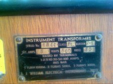
A CT really is a real transformer and works exactly like a real transformer.

But you are right, a Hall magnetic senor can be, and often is used to measure dc and ac current, and might be more accurately said to be a type of current transducer.

For people like myself that are severely mathematically challenged, there are on line calculators to number crunch Mr Faraday's amazing law.
https://www.daycounter.com/Calculators/Max-Flux-Density-Calculator.phtml
 
Last edited:
Thinking for some of us, this is a fascinating look into a realm many are not familiar. Just now I asked chatGPT (artificial intelligence) this question. Feel free to ask more practical questions and I can try it.

3CB69B54-BE1F-421B-B29E-97E76BD08471.jpeg
 
How about probing ChatGPT with similar questions on other topics, to better understand it?
This will expose how broad a vocabulary and sentence structure it offers.

"Can a zip gun fabricated from a car antenna function well enough as a self-defense weapon?"

"Can a respirator fabricated from a coffee filter protect against Covid as well as an N95 mask?"

"Does fruit fly like a banana the way time flies like an arrow?"

"What is the meaning of, 'The vodka was good but the meat was rotten'?"

Also,
"What toroid materials would be best for use in a DIY wrapped current transformer?"
"What toroid properties are best for making a DIY wrapped current transformer?"
 
I suppose it depends what you want the current transformer for.
In many applications extreme instrumentation grade accuracy is not really required.
I can think of a few applications such as inrush current measurement, or overload protection, where something fairly crude would work just fine.
 
How about probing ChatGPT with similar questions on other topics, to better understand it?
This will expose how broad a vocabulary and sentence structure it offers.

"Can a zip gun fabricated from a car antenna function well enough as a self-defense weapon?"

"Can a respirator fabricated from a coffee filter protect against Covid as well as an N95 mask?"

"Does fruit fly like a banana the way time flies like an arrow?"

"What is the meaning of, 'The vodka was good but the meat was rotten'?"

Also,
"What toroid materials would be best for use in a DIY wrapped current transformer?"
"What toroid properties are best for making a DIY wrapped current transformer?"

Can you give a specific function that the CT is to do?
 

Attachments

  • 85C4A353-BA50-4BAA-8BC6-C5C0598CC4AA.jpeg
    85C4A353-BA50-4BAA-8BC6-C5C0598CC4AA.jpeg
    91.4 KB · Views: 43
ChatGPT does sound somewhat like the character Data in Star Trek Next Generation. But I was hoping for somewhat technical questions without too much depth, beyond its capability.
 

Attachments

  • 2B5F1B7B-827A-48A7-870B-57EACD93CE43.jpeg
    2B5F1B7B-827A-48A7-870B-57EACD93CE43.jpeg
    133.8 KB · Views: 10
Magnetics have some free design software for designing current transformers.
Never used it personally, although I have a CD around here somewhere with the original now very old software on it.
Magnetics only make powdered iron toroids and ferrite toroids, so their current transformers only work at much higher frequencies.
They don't make metal cores suitable for 50/60Hz though, so probably useless for what you are doing ?
It may provide some insight though.
This may be the same, or maybe an updated version ?
https://www.mag-inc.com/design/design-tools
 
85c4a353-ba50-4baa-8bc6-c5c0598cc4aa-jpeg.131250


I guess ChatGPT is unfamiliar with his ancestors' attempts at processing natural language.
The above statement was the outcome of English --> Russian --> English for "The Spirit is Willing, but the Body is Weak."
(According to my computer science education.)

I wonder how much human guidance went into ChatGPT's knowledge, vs. just having it read everything on the web.
It does seem to regurgitate general statements.
In that regard, it may be more accurate than most humans and more approachable than printed FAQ.
Throw in a little malicious hacking ...
 
Apparently, according to the Oracle, iron powder, ferrite, and permalloy all have high permeability .

That is like saying ants, mice and elephants are all large animals.

From the perspective of a virus, that may be a defendable statement.
 
Last edited:
That video is pretty interesting, he certainly knows his stuff.

Notice the steel washers, no powdered iron, no ferrite, no permalloy, just real steel.
The only disadvantage of using relatively thick steel washers, will be fairly high eddy currents created in the steel.
But he minimizes that problem by insulating the washers from each other, and using a summing amplifier, which in effect becomes a zero ohm burden resistor with some gain.

The induced current tends to take the easiest path, and the steel has a pretty low resistance, but the input of a summing amplifier is also a very low resistance, zero ohms in theory, so it tends to still get its fair share. This would not work very well with a conventional burden resistor, even a very low value one. The opamp is the magic ingredient that allows it to work reasonably well.

A more efficient approach would be to salvage the laminated steel E and I stampings from a small mains transformer. But of course it all then becomes a lot larger. The thinner steel stamped laminations greatly reduce the eddy current problem. A current transformer does not need to be a toroid, the usual familiar rectangular E and I transformer geometry works just as well.
 
Is a $0.40 CT any good? What differentiates a good CT from a bad CT? The only thing that I can see manufacturers could play around with are: core material, wire material, wire gauge, and number of turns.

I don't think the materials make any difference in the end if you can calibrate around them. That leaves the gauge and windings.

First, characteristics of various AWGs:
AWGmΩ/ftA (60 °C)A (ΔT0)
22​
16.14​
3​
0.9​
26​
40.81​
1.3​
0.361​
30​
103.2​
0.52​
0.142​

Next, I looked at the ESP32s, the 20 ADCs @ DB11 have a range of 0 to 2500mV with +/- 10mV (slightly more accurate at lower voltages).

Fired up a spreadsheet to look at the numbers:
30 AWG - 100 turns30 AWG - 1000 turns
1675964992062.png1675965044874.png
The red 0.15 is the maximum safe current for 30 AWG, so 100 turns limits the maximum number of amps that can be measured.

You can use any value of Rs to adjust the voltage, but I picked one that would give the maximum voltage spread for the maximum current.
Using a 15Ω resistor gives a voltage range of 0 to 2.34, but the accuracy is going to be sketchy at less than 12W.

At 1000 turns and 160Ω, there's no issue with the current even at 60 amps, but the voltage is a little more spread out. So, you could use a 35Ω resistor and get a reading for 0 to 60 amps, but the precision would be less. If you went with a 160Ω resistor and limited it to 15 amps you get the same precision as the 100 turns.

What about wire gauge? Similar to more turns, it allows higher currents. But the precision range remains the same.
1675965577963.png

The math represents the theoretical case, in practice, the values will probably be less.

The IotaWatt is said to be, with calibration, within 1%. So, suspect a 50 amp CT would be good within (60x120x%1) 60 watts.


So, the take-away on this is use the lowest amp CT you can, and if you can calibrate the CT and treat each one differently the cheap ones are probably as good as the more expensive ones (although I'd test the resistant to validate the gauge).
 
The core material, structure, and treatment makes a huge difference in performance.

If you can calibrate around the differences, software is cheaper (when deployed in volume) than hardware.
But I always like to rib software guys that hardware is cheaper, faster to develop, easier to update, more reliable than software.

Poor core performance may result in less signal, and less signal to noise, than you might otherwise get.
I think large hysteresis will increase the amount of current swing in primary vs. signal in secondary.

You could get samples of several types, stimulate with various signal amplitudes and frequencies, measure the results.
Use multiple frequencies at once, to see non-linear effects.

My application relied on passive coupling, so core performance was everything.
 
ESP32 ADC linearity is not particularly great. Okay if you stay between 0.15v and 2.70v for 3.3v supply with scale offset correction.

ADC correction curve.png
 
Definitely agree core material, structure, and treatment makes a huge difference to performance.

There are several very different parameters that you need to stay well inside of if its going to work in your application.
Neglecting the turns ratio, which obviously has to suit your application, the first limitation is the max continuous current rating.
As with any type of transformer, the maximum continuous current limit is set only by safe temperature rise of the wire and the insulation.

If you try to measure twenty continuous amps with a ten amp rated current transformer, its going to get very hot indeed.
It will work though, and be quite accurate too, but probably not for very long.

The next limitation is the voltage and the frequency across the windings. Both need serious consideration. As with any transformer, the core material will have a limit for flux density beyond which it saturates. Too high a voltage or too low a frequency will definitely saturate the core, and transformer action stops. Before it stops altogether, the transformer will become very non linear in operation, not something you really want in high grade instrumentation.

And lastly, any transformer will have a self resonant frequency due to capacitance between turns. For any transformer you must stay well below this self resonance if its going to behave in a linear predictable way.

Now the problem is, you cannot have everything. Current transformers are made to work within certain limits for particular applications. Some characteristics are sacrificed to gain more of something else needed for a particular application.

Its rather like batteries.
Batteries come in a huge range of sizes, chemistries, and number of cells, and you choose something suitable to do a particular job.
But the battery you have, may be totally unsuitable for a completely different application.

Likewise current transformers are purpose built, and may work well for you, or maybe not at all. Something suitable can usually be selected from published data, or failing that, some practical measurement and testing may tell you if its going to do what you want it to do.

Unfortunately much of the Asian stuff is not very well documented, and something you might really need to know is not even mentioned, and often its a case of taking a chance, and then testing what eventually arrives.
The people selling the stuff often have absolutely no clue, so its usually useless asking some sales person for further details.

I have accumulated a good stock of various CTs over the years, and can usually find something I already have that will work in a particular project.

I strongly disagree that any problems can just be calibrated out with maybe a lookup table. If its totally the wrong type of transformer, or being used inappropriately, its often not a big deal to find something else much more suitable that does work.
 
Last edited:
Is a $0.40 CT any good? What differentiates a good CT from a bad CT? The only thing that I can see manufacturers could play around with are: core material, wire material, wire gauge, and number of turns.
There are a few other very important pieces of the jigsaw puzzle including the magnetic length of the core and the magnetic cross section of the core. These extra factors have a very great effect upon the inductance, flux density, and self resonant frequency.
I don't think the materials make any difference in the end if you can calibrate around them. That leaves the gauge and windings.
Not true.
If the transformer is incapable of operating under the conditions it is placed under, you cannot calibrate around the fact that it simply does not work.
First, characteristics of various AWGs:
AWGmΩ/ftA (60 °C)A (ΔT0)
22​
16.14​
3​
0.9​
26​
40.81​
1.3​
0.361​
30​
103.2​
0.52​
0.142​

Next, I looked at the ESP32s, the 20 ADCs @ DB11 have a range of 0 to 2500mV with +/- 10mV (slightly more accurate at lower voltages).

Fired up a spreadsheet to look at the numbers:
30 AWG - 100 turns30 AWG - 1000 turns
View attachment 134054View attachment 134055
The red 0.15 is the maximum safe current for 30 AWG, so 100 turns limits the maximum number of amps that can be measured.
Yes totally correct.

You can use any value of Rs to adjust the voltage, but I picked one that would give the maximum voltage spread for the maximum current.
Using a 15Ω resistor gives a voltage range of 0 to 2.34, but the accuracy is going to be sketchy at less than 12W.
Maybe ??
Rs determines the voltage across the secondary generated at the particular secondary current.
The higher Rs the higher the voltage, and the higher the flux swing needed in the core to generate that extra voltage swing.
At some point the core is going to saturate.
The way to fix that is either use a fatter core with more cross section to lower the flux density (for the same total flux) or Reduce both Rs and the voltage. If you aim for 250mV instead of 2.5V that reduces the required flux swing in the core to one tenth.
CTs are always rated for a particular maximum output voltage at a minimum specified frequency, and if you want good linearity is always good to stay well within the max output voltage swing rating.

At 1000 turns and 160Ω, there's no issue with the current even at 60 amps, but the voltage is a little more spread out. So, you could use a 35Ω resistor and get a reading for 0 to 60 amps, but the precision would be less. If you went with a 160Ω resistor and limited it to 15 amps you get the same precision as the 100 turns.
You need to stay within both the current the wire can carry, and the maximum rated output voltage. Below those two limitations you can play around with Rs and output voltage to scale your current measurement. If you need a higher output voltage than that to drive an A/D converter, an amplifier may be required if the CT does not have enough grunt to generate the required output voltage.
What about wire gauge? Similar to more turns, it allows higher currents. But the precision range remains the same.
View attachment 134056
Yes, but the big wire with more extra turns all needs to fit onto the core. Bigger core costs more and may quickly become inconveniently large.
Its easy to go big and get much better performance, but nobody wants to spend the cash to do that. All this is usually a commercial enterprise driven by profit. If you are making your own CT, then going big has many advantages, like being much easier to wind and probably more reliable.
The math represents the theoretical case, in practice, the values will probably be less.

The IotaWatt is said to be, with calibration, within 1%. So, suspect a 50 amp CT would be good within (60x120x%1) 60 watts.


So, the take-away on this is use the lowest amp CT you can, and if you can calibrate the CT and treat each one differently the cheap ones are probably as good as the more expensive ones (although I'd test the resistant to validate the gauge).
Maybe, it depends on your requirements. You can go cheap and small and accept the limitations of linearity and accuracy.
Or you can go larger and have much better overall performance at a higher cost. There is no single correct answer.

The trick as with any engineering is to define your needs and select the appropriate parts.
 
What this application needs is a good non-linear resistor.

I tried to use a diode for that purpose, when I was asked for 5 orders of magnitude current sensing. Bad temperature response, of course. I determined that 2 or 3 orders of magnitude was all they needed and put in a better resistor.

If you could find a way to have a non-linear resistor, or low/high range switching (without anything getting blown up), might get the range and resolution you want.
 
Auto ranging is the usual solution to this problem.
Multimeters these days can measure from millivolts to hundreds of volts by fully automatic range switching.
Current transformers can also have tappings that can be switched, either in the primary or secondary.
 
How about two windings on the CT, each with different resistors? Like 20A and 200A range?
Then it's just muxed ADC input. Except, when the low-current output is full range the other is over-range. Series resistor on output, clipped with diode to supply rail?

I haven't done much with them except measuring my AC line voltage circuits, usually with scope.
But I've got some ideas on detecting grid input current to my inverters and using for relay control purposes.
(Trying to use 3x Sunny Island as phase converter between split-phase grid and 3-phase circuit. Presently, only one can connect to grid L1 by relay, 56A limit. Would like another 56A from L2.

The designs I did were measuring emission current and the like. And Faraday Cup current. pico/nano/micro/milliamp. Also filament current about an amp. All DC, but some interference issues.
 
Yes indeed.
Multi winding current transformers have been around for a very long time.
I bought this monster at an auction, genuine original state of the art 1940s technology.
It has a five amp secondary that goes with an associated power meter which has an inbuilt 7.5 ohm burden resistor.

One turn through the big hole is the 1,000 amp range.
As it says on the rating plate, 2 turns, 500 amps, and 5 turns through the hole 200 amps.

For lower current there are alternative primary windings already on the current transformer, and you connect your current through the appropriate large brass terminals on the top of the transformer. Available ranges go right down to 1 amp.

An interesting bit of kit I have owned for many years and never used.
 

Attachments

  • 2023-02-10_0002.jpg
    2023-02-10_0002.jpg
    622.4 KB · Views: 6
  • 2023-02-10_0001.jpg
    2023-02-10_0001.jpg
    951.6 KB · Views: 6
Wow! Interesting ideas!

...What this application needs is a good non-linear resistor....
Doesn't have to be a resistor either, as it's AC it could be an inductor...but AFAIK that's only non-linear with frequency.
 

diy solar

diy solar
Back
Top