diy solar

diy solar

DC Power Distribution

webbbn

Solar Enthusiast
Joined
Aug 9, 2023
Messages
345
Location
Arizona
There may be a thread on this already, but I didn't see it.

I tinker with alot of electronics, and a few years back I decided to make a few high(er) current DC power supplies that I put octopus wires on so that I would have easy access to 12V and 5V power for whatever devices I wanted to power without hunting down a power adapter and then finding a plug to plug it into.

If you have a solar battery putting out kWs of 48V DC, does it make sense to power at least some devices off that directly and skip the DC->AC->DC conversion? Of course, there's going to be additional line losses with lower voltage and losses in DC-DC conversion, but it may end up being overall less loss, and it could reduce the inverter power requirements.

A quick google search suggests that 48V would be considered low-voltage, which would ease code restrictions. Of course, you're going to want to make sure you use proper fuses when connecting to your gigiwatt battery bank.

I've seen proposals for multi-voltage DC outlets, but they never seem to go anywhere. Do such things exist? USB-C is becoming pretty standard, and it supports multiple voltages. I suspect DC power is also more common in RVs and boats, but I'm not very familiar with what's available or what the standards are.

A while back I found some A15 standard 12V LED bulbs, and wired up some post lights in the yard to low-voltage landscape lighting. Seems like that could/should be more common. You should be able to power 4 12V LED bulbs directly from 48V if you wire them in series, with no conversion loss, assuming they haven't done anything fancy internally, and just wired the LEDs in series with appropriate resistors.

Thoughts?
 
If the loads are fairly close to the battery. Of very low power draw (like led lighting), then it makes perfect sense to have Direct from battery loads.
I have one 48v DC mini split. And will be adding a couple more. For the reasons you mentioned.
 
There have been talks of using Power-over-Ethernet for low voltage lighting and similar applications for years that have always stalled. The cost per port seems to have been the biggest factor in their death, as the cost of an enterprise switch was something around $70/port, plus a $100 cost per drop. Using passive POE and a separate cable plant (Cat 3 or 5e instead of 6+) got that combined cost closer to $100 per fixture but if the competition is an extra 20' of MC cable and a wireless communications/control interface it is still about double the increment. It could make sense in some conditions, but you ultimately needed to cut the cost by at least half.

I am curious what would make a better standard though. It seems like a 48VDC branch circuit supporting 300W maximum could be pretty useful.
 
USB charging standards are pretty good now for power negotiation by devices. I would consider putting something like you suggest (48VDC with one or more standard power levels) to outlets, and putting USB-type chargers as outlets. If would be nice if the chargers were user replaceable so they could be upgradable.

I wouldn't think there would be a problem running 48VDC over existing AC wiring to retrofit some outlets, which should support up to 1kW for 20A circuits.

You should also be able to easily and cheaply make 48VDC bulbs by just stringing enough LEDs together.
 
I have a vintage 1974 sailboat that has both a 12 volt DC wiring system and a 120 vac wiring system onboard.
The AC receptacles are the standard 3 prong receptacles. There is one DC receptacle and it is one of the old two prong AC receptacles without a ground pin.
I think this was their standard DC wiring on the boat back in 1974. It has a factory engraved legend plate over the outlet saying 12V DC. At first I thought it was a bit crazy, but if you make a mistake and plug in a 120 VAC device into a 12 volt DC outlet, what is likely to happen? Not much in most cases. 12 volts of DC on a 120 VAC device is likely to draw very little current and if there is a problem, the 12 volt fuse that feeds the outlet will pop. So that's something to think about. If you did that you could use standard off the shelf receptacles and plugs that have orientation - they can only go in one way. I wouldn't try to pass a code inspection with this, but from a practical standpoint, it would probably work. Just make sure to install fuses or breakers rated for DC to protect the wiring.
 
You should be able to power 4 12V LED bulbs directly from 48V if you wire them in series
Depends on internal voltage/current regulation circuit inside those 12v lamps. There would be nothing to balance voltage across each light but the current load of each light. If one light turns on last then it may see 40V across the input. Better idea is to go with 48V LED light or wire enough bare LED chips in series with correct current limiter to run on 48V.
 
Depends on internal voltage/current regulation circuit inside those 12v lamps. There would be nothing to balance voltage across each light but the current load of each light. If one light turns on last then it may see 40V across the input. Better idea is to go with 48V LED light or wire enough bare LED chips in series with correct current limiter to run on 48V.

LEDs are (for the most part) constant voltage devices, so the LEDs balance the voltage. That's the way they work, and wiring them in parallel is standard practice.

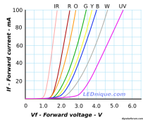
This is an example voltage/current curve for LED of different wavelengths:

1698970290372.png

A specific LED will then have a (fairly large) range of current that it can support, where the brightness is dependent on the current. Pick the right number of LEDs to hit the spot on the curve that you want and you're good. Add resistors to drop voltage if you don't need that many LEDs.
 
LEDs are (for the most part) constant voltage devices, so the LEDs balance the voltage.
Yes that's why I said depends on internal voltage/current regulation circuit inside those 12v lamps. If each light has simple resistor as current limiter then you are fine. If they use linear regulators you are probably also fine. If it's something fancier like dc-dc switching regulator then you may get in trouble.
 
Yes that's why I said depends on internal voltage/current regulation circuit inside those 12v lamps. If each light has simple resistor as current limiter then you are fine. If they use linear regulators you are probably also fine. If it's something fancier like dc-dc switching regulator then you may get in trouble.

I may be missing something. What internal voltage/current regulation? Why would powering LEDs from a switching power supply be a problem?
 
I do it. Most everything in my shop runs off the 48V. Safety is the goal. That's a lot of power. And it goes many places. Everything mounted to DIN rails on a fireproof backboard and shielding: terminal strips, DC breakers, DC fuses, DC voltage converters to 24, 20, 12, and high power USB-C modules. Once it makes it to USB-C, the safety risk is much lower like household electronics.

Be aware any small capacitor with 48V under stress of high frequency switching can at any time spray hot oil and the aluminum plates still connected to 48V can ignite that electrolyte and nearby plastics. If there's high voltage DC (like distribution from your EV) a fully enclosed NEMA rated or equivalent enclosure and metal conduit is a must. And it should be separated from the low voltage DC. I have seen circuit breakers catch fire when trying to "open circuit" more than once. Use rated fuses to lower the risk. And the enclosures even further. Enclose everything if you can. If there's a failure, and there will be, will it contain it?
 
Why would powering LEDs from a switching power supply be a problem?
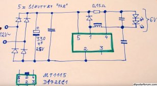
Switching regulators with their inputs connected in series may not share input current equally and that will result in different voltages across each input. May result in voltage oscillations or overvoltage and damage. Here is schematic of 12v light that uses buck dc-dc regulator. Source.
12v_light.JPG
 
You don't need all that. This is not a theoretical discussion. It's how DC LED lights are made.

 
You don't need all that. This is not a theoretical discussion. It's how DC LED lights are made.

Someone decided they do need all that because they made the bulb-maybe only for a specific application-but it is there.
 
At first I thought it was a bit crazy, but if you make a mistake and plug in a 120 VAC device into a 12 volt DC outlet, what is likely to happen? Not much in most cases. 12 volts of DC on a 120 VAC device is likely to draw very little current...
For resistive loads that would be true. But many AC devices are current limited by their impedance not their resistance. For example, an AC fan motor might pull an amp at 120 volts, but because it has a small DC resistance 12 volts will burn it up.

One thing off-griders have done is to use 240 volt receptacles and plugs for their 12 volt circuits so that no 120 appliances could accidentally be plugged in.
 
The standard outlet used to be the 6-15.
Because it was not normally used in AC systems.
 
Switching regulators with their inputs connected in series may not share input current equally and that will result in different voltages across each input. May result in voltage oscillations or overvoltage and damage. Here is schematic of 12v light that uses buck dc-dc regulator. Source.
View attachment 175865

I re-read my original post, and I think I understand what you're saying. You're talking about what might be in the bulbs, not external to the bulbs.

I did mention that having a switching regulator in the bulbs could be a problem, but I really doubt that would be the case. Why add all the cost of a switching regulator to, in effect, reduce the light output of the bulb.
 
More efficient vs. linear or resistor regulator and eliminates flicker if powered from AC.
 
Back
Top