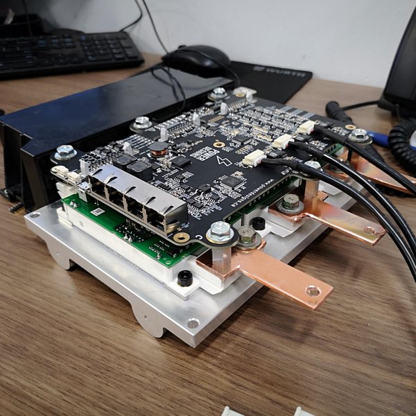
I sat down and looked at my driver board for a bit, analyzed the drive circuit with a multimeter and made a mental schematic of it. Really weird setup for the negative gate drive, but here we go.
1) 12v power comes in through the input. A UC3843A pwm driver IC drives a 80N75 mosfet, which pwms the 12v at 500khz into a ~0.2ohm winding in the transformer. The transformer then has 3 isolated ~0.4ohm windings, which are connected each to their own 35v 100uF electrolytic in series with a diode. We now have three isolated 30v sources. One is shared between the low side IGBT gates (which don't require isolation, one gets a 60Hz square wave and the other outermost one 23kHz swpm) and the other two go to each of the high side IGBT gates which require isolation, the outermost is driven by 23kHz down and the innermost gets the 60Hz square wave. So the two resistors that heat up are the outermost ones, the inner ones are perfectly cool.

2. On the backside of the board, there are three L7824cv 24v (1.5A) max regulators that each take the 30v and turn it into 24v and pass it back to the front side of the board.

3. Now back to the front, this is where it gets weird. The 24v is put into two 35V100uf caps in series. Now, in a normal scenario it would be split up almost perfectly 12v and 12v between the two. But there's what seems to be a 5.6v Zener diode in parallel with the left capacitor. So, the voltage is split around 5.6-5.7v on the left capacitor and 18.5v on the right.

And then of course the NPN and PNP transistors switching with the point in between the two capacitors referenced as ground, so they switch -5.6v and +18v from the caps into the gate.
This is what worries me, because if the left capacitor (5.6v, used for negative driving) has more draw than the right at any moment (when turning gate to low, for example) all the voltage would shift to the right one, and possibly bring it above 20v?
So when the gate is first turned high, all is good, but when turned low, the right capacitor might charge above 20v, and can't discharge cause of the diode. And given that the maximum gate voltage is +-20v for the igbt, it could explain the excessive heat generated from the resistors, if it's trying to push more than 20v into it.
I'll probe it probably tomorrow and see if the voltage in the caps fluctuates significantly when switching. I have a plan if it has problems.
Also
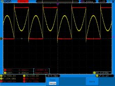
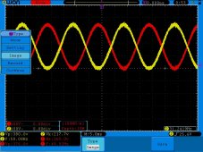
@Bob, the power draw of the driver board is exactly the same with and without any collector voltage, and remains constant from 0-33v, scoping the gate it doesn't have the peak anymore though.


 hackaday.io