diy solar

diy solar

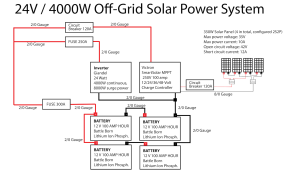
Does this schematic of my project contain planning errors?

Here is a drawing that will look confusing at first but it just shows what connects to what.
It can be further tweaked when we know the size of the wires on the converter.
The legend block describes all the elements.
I see the legend but not the drawing or am I not looking in the right place for the drawing? Thank you for this!!
 
2 negatives does not mean isolated. The specs specifically say it is not isolated. If unsure test for continuity between the 2 negatives.

I see nothing in relation to grounding in your diagram. PV in series is 80+v open circuit. Strongly advise coming up with a grounding plan.
Good catch. I'm planning to connect the PVs 2S2P but I suppose grounding is always a good idea. Is there a resource regarding grounding approaches you would recommend for this kind of system? Thank you!
 
Thank you!
The reason I suggest that is then you don't need to have one odd-ball maxi fuse in your system.
Those converters are pretty cheap and nasty so I don't trust there ratings.
I see the legend but not the drawing or am I not looking in the right place for the drawing? Thank you for this!!
The main part of the drawing "dc_domain" its just a textual representation of what connects to what.
The systems we make are like a ladder.
The busbars are the risers and the circuits are the rungs.
In other words every circuit connects between the positive and negative busbars.
 
The reason I suggest that is then you don't need to have one odd-ball maxi fuse in your system.
Those converters are pretty cheap and nasty so I don't trust there ratings.

The main part of the drawing "dc_domain" its just a textual representation of what connects to what.
The systems we make are like a ladder.
The busbars are the risers and the circuits are the rungs.
In other words every circuit connects between the positive and negative busbars.
Interesting. Can't wait to mentally master all these things.
 
So this means I would replace the current 25A fuse for the converter, with 30A, right?
20 amps 12 awg on the "in" and 30 amps 10 awg on the "out".
Is 25 amps enough for your 12 volt loads?
 
The amazon link says the converter is non-isolated.
You should check for continuity between the negative wires before you connect the converter.
 
Good catch. I'm planning to connect the PVs 2S2P but I suppose grounding is always a good idea. Is there a resource regarding grounding approaches you would recommend for this kind of system? Thank you!

Exactly. 2s means 80+v on the PV circuit. That is classified as high voltage. about 1/2 A of current can kill.

This link is the start of a 4 part tutorial on grounding.


As for the converter, like I already said, it is not isolated. Since you're using a distro panel where each 12v circuit should be individually fused, I would just make sure the 24v side is fused low enough that a short on the 12v side will blow it. This way you at least don't have to worry about also fusing the link to the distro panel. Since the other guy is helping with that, you should ask him about it. I don't want to cause confusion but there's also no need for you to be jumping through unnecessary hoops.

I'll bow out now, but will continue to watch the thread. Feel free to tag me if you have a question. Good luck!
 
Last edited:
Wow. "Less than 1/2 A of current can kill." That got my attention. I'd like to stay alive. Is there a top-five list of sorts for what to do to stay alive when putting together a DIY solar system?
 
Wow. "Less than 1/2 A of current can kill." That got my attention. I'd like to stay alive. Is there a top-five list of sorts for what to do to stay alive when putting together a DIY solar system?
Let me elaborate, less than 1/2 A across the heart. In order for it to jump the skin barrier, the voltage has to be high enough, (I believe 30+ volts is high enough, though i'm not too clear on this) but anything above 50v definitely is. So yes, electricity is dangerous. Be careful.
 
You bet. I will study the 4 manuals on grounding you reference. It would be good to have a comprehensive safety guide of sorts focused on all the things that can go wrong safety-wise, from being electrocuted to sparks getting in your eyes. I'm sure it exists.
 
You bet. I will study the 4 manuals on grounding you reference. It would be good to have a comprehensive safety guide of sorts focused on all the things that can go wrong safety-wise, from being electrocuted to sparks getting in your eyes. I'm sure it exists.
Sure, off the top of my head I can tell you this: use safety glasses, use insulated wrenches/ratchets/tools, never work with live conductors (kill a breaker, cover a PV panel with cardboard, turn a disconnect, etc) if you can help it. Sometimes you can't E.G when making a battery connection. Connect the wire to the fuse side first. Then connect the wire to the battery. No live wire ends floundering loosely around. Also, wear insulated gloves if you must work with live high voltage. Probably most important is: do not get in a hurry. Be methodical. Check and double check. Maybe even have someone else review your work.
 
Sure, off the top of my head I can tell you this: use safety glasses, use insulated wrenches/ratchets/tools, never work with live conductors (kill a breaker, cover a PV panel with cardboard, turn a disconnect, etc) if you can help it. Sometimes you can't E.G when making a battery connection. Connect the wire to the fuse side first. Then connect the wire to the battery. No live wire ends floundering loosely around. Also, wear insulated gloves if you must work with live high voltage. Probably most important is: do not get in a hurry. Be methodical. Check and double check. Maybe even have someone else review your work.
Thank you, @DerpsyDoodler !! Maybe you just saved my life ;-)
 
Are you using busbars?
Suggest you use a fused positive busbar and an un-fused negative busbar.
You should have a battery fuse.
You may want a disconnect switch between the batteries and the positive busbar.
You should have a double pole single throw switch between the panels and the charge controller.
I don't see a shunt, you probably want one.
2/0 is overkill except for the battery and inverter circuits.
Good day, @smoothJoey - where would the shunt go and are there certain specs for it I should look for? Thank you.
 
I notice you tagged joey, but I saw it and was here. Based on your system size, you could probably get away with a 250A shunt. 500A wouldnt hurt and would give you room to grow if you add larger DC loads or upgrade the inverter.

Where you place it depends on the shunt. Some get placed on the positive lead of the battery bank, some on the negative side. Key point to note is the shunt sits between the battery and the loads/chargers: battery bank <--> shunt <--> loads (inverter, converter, etc)/chargers
Thank you, @DerpsyDoodler
 
I've been upgrading my off-grid-solar-rig work-in-progress project with a more powerful charge controller and more batteries as shown in the schematic below. I'm uncertain about whether the fuses and wires are adequate, too little or too much. I'll be grateful for your advice on this and on anything else that catches your eye. Thank you!!

Marc 24 W solar schematic - ver B-01.png
 
I've been upgrading my off-grid-solar-rig work-in-progress project with a more powerful charge controller and more batteries as shown in the schematic below. I'm uncertain about whether the fuses and wires are adequate, too little or too much. I'll be grateful for your advice on this and on anything else that catches your eye. Thank you!!

View attachment 94620
There's a voltage drop calculator in my signature. Use it to determine the wire size you need. At first glance, it serms like 2/0 is overkill for your MPPT-battery connection. Note that length means the total length of the circuit round trip (bat pos to load pos, load neg to bat neg). So for instance, if battery is 10 ft from inverter, round trip is 20 ft.

The load negative needs to be connected to the other battery negative post in order to keep the bank balanced. Otherwise you'll draw and charge more from the first 24V battery in that parallel bank.

Search the forum for ways to wire parallel batteries. There are multiple examples. What I describe is the "diagonal" approach.
 
Back
Top