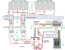
Notable design considerations:
*)Off grid
*)Principle requirement is to provide 24x7 power in event of extended grid power outage.
*)Secondary requirement is to supplement home power and offset grid power usage and expenses.
*)Scaled for full-time 24x7 off-grid power for fridge, entertainment center, main living room lights/outlets/ceiling fans, kitchen outlets, master bath.
*)120VAC only. Will not power 240VAC circuits for AC, pool. Might power washer/dryer (gas, 120V)?
*)100% redundant panel/charge-controller/battery: 2 batteries, 2 charge controllers, 2 panel strings. Each can be operated independently of other or in parallel.
*)DC PV string output is MOC 75VDC. Anything over 80VDC would have required additional arc-fault detection/mitigation (more $$).
*)Used panels. 8x250w. 4 permanently installed. 4 other panels can be hung in minutes next to them for long-term (more than a week) if needed.
*)3000W WZRELB 120VAC/36VDC sinewave inverter.
*)2x60A MakeSkyBlue v118 MPPT charge controllers. Design has each pushing a maximum 20A charge current into batteries
*)16kwh 36V lithium ion battery made from 2021 Ford Mach-E modules. Turn-key: Minimal amount of work to get these operational.
*)Conductors fabrication, breakers/fusing, labeling scaled as outlined in general electrical code/best-practices and NEC 710.
*)Designed using "NEC 690 Standalone System" guidance. Considerations
*)PV&ESS/&Inverter-out disconnects integrated within generator unit.
*)using 2020 NEC 706 guidance for ESS implementation
*)No grid interconnect (NEC 705?)...is standalone with power transfer (Using NEC 710 guidance) to select circuit (total 125% amps of selected circuits under rated capacity of generator design).
*)Reliance 6 circuit transfer 30A switch
*)Old-school electrical monitoring using analog panel meters. They ALWAYS display panel/battery/AC voltages even when unit is off. Cell voltage is monitored separately while inverter is in use or panels are charging. All are 200ma fused.
*)HUGE red disconnects (1 for each PV string, and 1 main that sits between battery and inverter). Signage on main panel and generator housing guide emergence responders to location&purpose.
*)Surge protection integrated into each PV string.
*)Total approach to engineering grounding solution.
-DC ground bus which connects to ALL DC component enclosures.
-AC ground bus which connects to ALL AC component enclosures, generator internal sub-panels, and generator chassis.
-AC and DC ground buses bonded within generator cabinet
-DC Negative power IS NOT bonded to DC ground.
-Verified each DC component's chassis does not internally "ground" to negative or positive terminals.
-Neutral and ground NOT bonded within generator cabinet or inverter (verified floating ground within inverter).
-Ground/Neutral Bond is at main load panel.
-Panel frames grounded with single 6 gauge bare solid copper. This connects to generator ground lug on exterior of cabinet.
-In addition has single earth ground connect to panel frame ground wire.
-If I ever decide to use generator as standalone (not connected to load panel) generator, I'll bond ground/neutral inside generator.
*)PS: Shade across left panel was
Last edited:


