diy solar

diy solar

Doubling the Number of Solar Panels

SteinVT

New Member
Joined
Jul 30, 2021
Messages
33
Location
Vermont
First a little background on my system. I have a ground based array with 32 Adani 365 watt bifacial panels. Each has its own Enphase IQ7-plus micro inverter. I live in Vermont where in the fall and winter has very few sunny days. During a sunny day, the panels will easily max out the inverters, but during the cloudy days not even close.

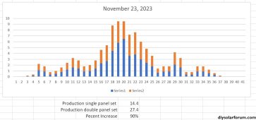
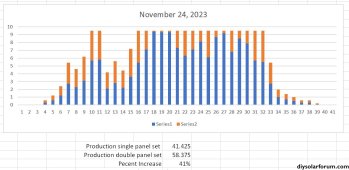
My thought was to remove half of the inverters and setup the two panels in parallel to drive each inverter. Install a second ground mount array just like the first to use the removed inverters.

By doing this I will:
  • Basically double my output of the array anytime the inverters aren't maxed out
  • Since I won't be increasing the max output, no new permitting
  • Won't have to upgrade my circuit panel or provide alternate attachment to the grid
  • Can use the existing wire runs from the array(s) to the circuit panel
The spec on the inverters says "Commonly used module pairings 235-440w +" with a note that says "No enforced DC/AC ratio". So I don't think it would hurt the inverters.

Does anyone know how to get the 15 minute data from Enphase? It would be very easy to calculate the additional energy collected over a year.

So is this a crazy idea? Thanks - Mark
 
Up front, no productive input on the Enphase, but I do have a question.
========
How much power do you expect to gain on cloudy days based based off data you have?
========
On my heavily overcast days, I can produce about 7% of the panels rated power. On a heavily overcast raining day, I get about 2% of the panels rated power. That’s 7 watts and 2 watts production per 100 watts. I’ve seen someone else report he gets 1/6th a panels rating throughout a heavily overcast day. That’s 160 watt hours per day on each 1 kW of panels.

For me, in those situations, no reasonable amount of solar can fix that. My needs for my RV are relatively modest 3 kWh per day to 20 kWh per day. A 2.5 kWbank can take care of that in sunny weather, but I’d need a 30 kW bank to meet my needs on cloudy days.

I know you have data on your system in Vermont that will be different than mine in Arizona.
 
On a good summer day I can produce 85kwhs. In the last seven days, my system produced 12, 18, 6, 55, 45, 3, 30, and 7 kwh for a total of 176 kwh. My guess is we would maximize on two days and produce about 316 kwh. I used daily data to extrapolate production over a year, basically doubling each day to a max of 85kwh. I know this is optimistic as there would be times of the day where the system would max out even if the whole day did not, but at least it is a data point. Production under these conditions was about 87% of a true doubled system. That why I asked if anyone knew how to get the 15 minute data.

The whole thought process started when I was listening to a Podcast where they were talking about solar in Norway. The commentator said the dark winters weren't a problem, because solar panels have gotten so cheap, you just add more. If I can do that without digging another trench and adding to my grid tie infrastructure and get substantial benefit, sounds good to me. Thanks for the response - Mark
 
With 2 panels on one microinverter you could exceed the voltage or current ratings of the inverter and damage it.
 
In series, I could exceed the voltage rating. In parallel I believe the inverter will limit the current to the max allowable. In full sun, my current panels produce more than the micro inverter will convert. I am just trying to increase output during the low light days. Mark
 
I am coming to the conclusion that as long as I add panels in parallel, it should be fine. Just need the data to see if it makes economic sense.

I pulled a couple of days worth data of the Enphase app. Doubling the panel input produced a 41% increase on November 24th. The micro inverters were limiting output. The orange represents the added power.

However if you look at the day before output goes up 90%.

I am working with Enphase customer support to try and get the data. They gave me data for a couple of days, hopefully they can get me a year's worth. - Mark
 

Attachments

  • Nov 23 production.JPG
    Nov 23 production.JPG
    208.5 KB · Views: 1
  • Nov 24 production.JPG
    Nov 24 production.JPG
    275.3 KB · Views: 1
The big limiting factor here is how large the wiring is in your trench… what is the wire gauge? If it is #12 then you will have a really rough time. Perhaps the fact that you have #12 is what is forcing you down this overpaneling microinverter path. I suspect you have 3 #12 or 1 #6 for the size of array you have.

I don’t think microinverters are that good of an architecture for a DIYer willing to do the math to set up a string correctly. Strings are have way more design flexibility in how they can be overpaneled. So I am concerned you have locked onto a suboptimal approach.

I have looked at the spec sheets for overpaneling microinverters quite a bit.

Most microinverters are not going to like series, as discussed earlier. That said, you can find the odd duck MLPE that takes up to 80V, and with low enough series cell count micros you can put two in series. 80V is also the trigger voltage for various code things so staying below that is good.

For parallel, you will likely run into max ISC or series fuse rating limits. AP systems and Hoymiles micros had more headroom in this regard, especially the HMS generation.

I would probably prefer a string inverter at the new array. You don’t have RSD requirements within a ground mount. String inverter under the new array would limit DC wiring to just the jumpers between solar panels. After that it’s same AC as microinverter trunks.
 
The big limiting factor here is how large the wiring is in your trench… what is the wire gauge? If it is #12 then you will have a really rough time.
With the same number of micro inverters, the max current remains the same. If the wire in the trench was fine before it should be fine now. It will spend more time at the max, but not exceed it.
I guess that assumes the wiring in the trench is already rated for the max output of the optimizers. That would be the normal set up, right.
Perhaps the fact that you have #12 is what is forcing you down this overpaneling microinverter path. I suspect you have 3 #12 or 1 #6 for the size of array you have.
I assumed it was the cost of the micro inverters and wire in the trench. I guess we should ask the OP.
It sure would be simpler to add a string inverter or more micro inverters to the new panels.
I don’t think microinverters are that good of an architecture for a DIYer willing to do the math to set up a string correctly.
Agreed, it seems like an especially odd choice for a ground mount.
Strings are have way more design flexibility in how they can be overpaneled.
True but for some understanding the limits (and doing the math) is tricky. That's why micro inverters took off, much less math and integrated RSD.
So I am concerned you have locked onto a suboptimal approach.
It's a bit late for that, he's already got the micro inverters.
I have looked at the spec sheets for overpaneling microinverters quite a bit.

Most microinverters are not going to like series, as discussed earlier. That said, you can find the odd duck MLPE that takes up to 80V, and with low enough series cell count micros you can put two in series. 80V is also the trigger voltage for various code things so staying below that is good.

For parallel, you will likely run into max ISC
If there is a hard limit on current with these micro inverters, this could become a very expensive attempt at saving money (of the old inverters don't survive the over paneling)
 
It's a bit late for that, he's already got the micro inverters.
I mean for the ground array expansion.

There are likely some scenarios where replacing 1/3 of the microinverters (based on my estimate that the system has 3 20A AC strings, which translates to 1/3 being the unit of replacement) works out simpler. 3.8kW-AC string inverters are a drop in replacement on 20A inverter circuits.

True but for some understanding the limits (and doing the math) is tricky.
OP is already going down the path of electrically min maxing and lawyering the microinverters beyond their standard electrical configuration, it’s not that far off to just learning to do strings.
 
the OP mentioned in his second bullet point, about permitting. A new string inverter would require permit or poco issues he is trying to avoid
 
Partial swap for string inverter or setting up export limiter will achieve the same thing.

I also generally do not agree with the camp that says adding panels but same peak limit is always OK. You would still change the way the graph looks, and you extend the hours that any bottlenecked equipment is heat soaked.
 
In series, I could exceed the voltage rating. In parallel I believe the inverter will limit the current to the max allowable. In full sun, my current panels produce more than the micro inverter will convert. I am just trying to increase output during the low light days. Mark
Interesting thought exercise.
Try 1 panel and see what happens.

Can you pull stats from individual Micro-inverters to see the difference?
 
With 2 panels on one microinverter you could exceed the voltage or current ratings of the inverter and damage it.
I have done multiple times with enphase micro inverters with 2 panels in parallel.
They just flat line, about 10% higher than their rating and so far [knock wood] i have not had a damaged micro inverter.
The modern enphase micro inverters are really overrated ac-dc
eg
IQ8 245 VA AC -> 235-350W DC panel input
IQ8H 384 VA AC -> 320-540W DC panel input.
 
Back
Top