diy solar

diy solar

Educate me: 48V DC Battery Fuses, Circuit Breakers and Switches

SunFarmer

New Member
Joined
Sep 14, 2022
Messages
37
Location
Maryland, USA
Hello Forum,

I’m working on the low voltage, high current DC portion of my system. I’ve settled on the layout shown in the diagram, at least for now (hoping to at least partially commission the system so I can claim the USA tax credit for this year).
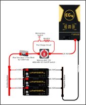
2022.1206.0000_off_grid_solar_wiring_diagrams.jpg
Initially, I was going to use a large DC circuit breaker between the battery bank and inverter. But then I read about resistance, voltage drop and fire caused by reversed polarity, so I decided to stay away from DC breakers. Then I saw David Poz’s excellent review of the Nader 125A breaker, my hope went up that it could be a good fit for me, until the end of David’s video where he had to take the current way above 125A for ten minutes before the breaker tripped. And the breaker got very hot in the process. Here gain I decided to avoid large DC breakers.

So, I chose to use a switch and a fuse, although I’m still not 100% sure about it. The best switch I could fine is only rated for 48V DC, whereas I wish it were rated for 60V. For over current protection I chose a 150A class-T fuse, which is just hair under my calculated minimum fuse size. I then realized that fuses, like breakers, can go way above their rated current before popping. What’s a DIYer to do?

Esteemed forum members, please provide your option on the best way to protect inverters, batteries and wiring from short circuits or other faults?

Thank You
 
Hello Forum,

I’m working on the low voltage, high current DC portion of my system. I’ve settled on the layout shown in the diagram, at least for now (hoping to at least partially commission the system so I can claim the USA tax credit for this year).
View attachment 123443
Initially, I was going to use a large DC circuit breaker between the battery bank and inverter. But then I read about resistance, voltage drop and fire caused by reversed polarity, so I decided to stay away from DC breakers. Then I saw David Poz’s excellent review of the Nader 125A breaker, my hope went up that it could be a good fit for me, until the end of David’s video where he had to take the current way above 125A for ten minutes before the breaker tripped. And the breaker got very hot in the process. Here gain I decided to avoid large DC breakers.

So, I chose to use a switch and a fuse, although I’m still not 100% sure about it. The best switch I could fine is only rated for 48V DC, whereas I wish it were rated for 60V. For over current protection I chose a 150A class-T fuse, which is just hair under my calculated minimum fuse size. I then realized that fuses, like breakers, can go way above their rated current before popping. What’s a DIYer to do?

Esteemed forum members, please provide your option on the best way to protect inverters, batteries and wiring from short circuits or other faults?

Thank You
You don't need a disconnect on the inverter circuit because each of the batteries has one.

6000 ac watts / .85 conversion factor / 48 volts low cutoff / .8 fuse headroom = 183.823529412 fault amps
You are using 2/0 awg wire which is good but your minimum fuse size should be 200 amps.
Your max size(which is my recommendation) is 300 amps.
Fuses protect wires not inverters.
Pure copper wire with insulation rated for 90C or better can be fused as high as 300 amps.
Higher rated fuses typically have lower resistance.
 
Last edited:
Just noticed you are using 6 awg.
The 125 amp breaker in the battery exceeds the ampacity of 6 awg pure copper wire with 105C insulation.
The batteries ship with 7 awg high temperature leads which are ok with the 125 amp breaker.
Its the difference in insulation rating on the wires that makes the difference.
 
Last edited:
Hello Forum,

I’m working on the low voltage, high current DC portion of my system. I’ve settled on the layout shown in the diagram, at least for now (hoping to at least partially commission the system so I can claim the USA tax credit for this year).
View attachment 123443
Initially, I was going to use a large DC circuit breaker between the battery bank and inverter. But then I read about resistance, voltage drop and fire caused by reversed polarity, so I decided to stay away from DC breakers. Then I saw David Poz’s excellent review of the Nader 125A breaker, my hope went up that it could be a good fit for me, until the end of David’s video where he had to take the current way above 125A for ten minutes before the breaker tripped. And the breaker got very hot in the process. Here gain I decided to avoid large DC breakers.

So, I chose to use a switch and a fuse, although I’m still not 100% sure about it. The best switch I could fine is only rated for 48V DC, whereas I wish it were rated for 60V. For over current protection I chose a 150A class-T fuse, which is just hair under my calculated minimum fuse size. I then realized that fuses, like breakers, can go way above their rated current before popping. What’s a DIYer to do?

Esteemed forum members, please provide your option on the best way to protect inverters, batteries and wiring from short circuits or other faults?

Thank You
The purpose of a fuse or breaker is to protect the wires from overheating/catching on fire. This and voltage loss is why we oversize our wires well beyond their theoretical capacity. Breakers usually use heat as a means of tripping and fuses actually burn out to protect the wire. Heat is expected in these protection devices. In proper design the fuse or breaker will not get close to its rated capacity unless you have a short in the system. Make sure you’re wires are large enough. Your fuses won’t protect your inverter that’s not what they are for.
 
I don't see it mentioned but I think you should put a fuse close to each battery before the positive bus bar. I think class T is the flavor most recommend.
 
Hello Forum,

I’m working on the low voltage, high current DC portion of my system. I’ve settled on the layout shown in the diagram, at least for now (hoping to at least partially commission the system so I can claim the USA tax credit for this year).
View attachment 123443
Initially, I was going to use a large DC circuit breaker between the battery bank and inverter. But then I read about resistance, voltage drop and fire caused by reversed polarity, so I decided to stay away from DC breakers. Then I saw David Poz’s excellent review of the Nader 125A breaker, my hope went up that it could be a good fit for me, until the end of David’s video where he had to take the current way above 125A for ten minutes before the breaker tripped. And the breaker got very hot in the process. Here gain I decided to avoid large DC breakers.

So, I chose to use a switch and a fuse, although I’m still not 100% sure about it. The best switch I could fine is only rated for 48V DC, whereas I wish it were rated for 60V. For over current protection I chose a 150A class-T fuse, which is just hair under my calculated minimum fuse size. I then realized that fuses, like breakers, can go way above their rated current before popping. What’s a DIYer to do?

Esteemed forum members, please provide your option on the best way to protect inverters, batteries and wiring from short circuits or other faults?

Thank You
Yes that schematic looks good.

You can switch your batteries off individually so I would remove that main disconnect. No real reason to have that and it's another component that could fail.

I would do 250A t class fuse for that size conductor and the surge for that LF inverter. 300A can work well too. Depends on your loads.
 
Just noticed you are using 6 awg.
The 125 amp breaker in the battery exceeds the ampacity of 6 awg pure copper wire with 105C insulation.
The batteries ship with 7 awg high temperature leads which are ok with the 125 amp breaker.
Is the difference in insulation rating on the wires that makes the difference.
Good point. And the distance is so short that the voltage drop differential between the packs would be minimal.

He could add a 4th battery as well.
 
The breaker is fine for individual pack protection. If you put more than 3 in parallel, a busbar and t class fuse is recommended.
If I understand correctly you are talking about a topology like this.
Code:
positive
|<->125A_breaker<->battery.1<->|
|<->125A_breaker<->battery.2<->|
|<->125A_breaker<->battery.3<->|
|<->125A_breaker<->battery.4<->|
|<->300A_class_t_fuse<->AIO<-->|
                        negative

In this topology the batteries can deliver 500 amps aggregate fault current.
The inverter circuit can pull 300 amps fault current.

If the inverter circuit over-current protection blows and fails to extinguish the arc, the plasma filament over the fuse gap will be very low resistance.
So the BMSs should start to disconnect in cascade within microseconds.
If one or more of the BMSs fail to disconnect then the battery breakers will trip in cascade.
IMO its nice to have a class-t fuse on the inverter circuit but not absolutely necessary because their are 2 more layers of protection.
This idea is part of a concept Bussman calls "selective coordination".

I've recently become aware of semi-conductor fuses https://diysolarforum.com/threads/class-t-vs-nh00-fuse.51693/post-656739
These semi-conductor fuses change everything but most of us are not using them... yet.

The Victron lynx products are a very popular modular busbar system which uses mega fuses for the branch circuits.
Mega fuses only have ~2000 amps breaking capacity at ~60 volts.
I think this is ok because of the selective coordination concept described above.

tl;dr
FET BMSs should trip before even a fast acting class-t fuse but not a semi-conductor fuse.
If the BMS fails the breaker is the last line of defence.
 
Last edited:
Everyone, Thanks for the wonderful feedback.

My inverter, batteries and battery cabinet are on their way from Signature Solar. Very exciting. Except I imagine my pallet of equipment duking it out with all the holiday deliveries.

Regarding the small battery cables, I will be using the short cables that come with the batteries. I thought I read that those cables are 6AWG, but I won’t know for sure until they are delivered.

Regarding a fuse for each battery, I’d love to be able to do that. But I’ve ordered the EG4 cabinet from Signature Solar and I will be using the busbars that are installed in the rack. Judging from the pictures, it doesn’t appear to be enough space to attach fuses to the positive busbar. If anyone figures out a way to add fuses to this arrangement, please share it with the community.

Regarding the beakers on the EG4 Lifepower4 batteries, the manual states “The included breaker is not a guarantee of battery protection. Size and install the correct overcurrent protection for conductors and battery”. Also, David Poz has a very good review of Gyll battery (which looks just like the Lifepower4) and in his video David intentionally overloaded the battery which made the BMS trip, but not the breaker. So those battery breakers may never trip.

Pre-Charge Circuit; In one of Will’s videos, he went through a series of steps to invoke the pre-charge resister on an EG4 battery. But the EG4 Lifepower4 manual states “the batteries are designed with an internal pre-charge resister to assist in starting large inverters. These resistors are active as soon as you turn on the battery’s breaker”. You simply turn on the battery! Does anyone have experience with using this internal pre-charge circuit? If so, please share it with the community. If it works, I’d like to eliminate the external pre-charge components and wiring from my design.

Regarding the large DC switch in my design, great input. I’m now hoping to eliminate the switch and simplify the wiring. It all depends on the feedback I get on the EG4 built-in pre-charge feature.

Thanks again everyone
 
@Will Prowse assures us that the breaker is fit for purpose.
The breaker is fine for individual pack protection. If you put more than 3 in parallel, a busbar and t class fuse is recommended.
Regarding the beakers on the EG4 Lifepower4 batteries, the manual states “The included breaker is not a guarantee of battery protection. Size and install the correct overcurrent protection for conductors and battery”.

@SunFarmer thanks for the dilligence.

Apparently Signature Solar is not standing behind their breaker.
What a mess.

@robby
@Tecnodave
@Will Prowse
@BenFromSignatureSolar
 
See this thread for added context.

 
Last edited:
So exactly what happens if there is a large load on the battery bank and someone opens that breaker? As I understand there will be a non-extinguishable arc across the contacts.

I scrapped the Fution powerwall due to poor quality build including AC breakers on the battery , etc.
 
Back
Top