diy solar

diy solar

EG4 18KPV - What not to do in parallel

Nothing you can show or provide.
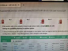
You've just got an 8-pin RJ-45 cable that connects the two jacks in some order.

What we're talking about is internal to the inverter, what function goes to each pin.
That way we can determine if crossover cable is identical to no cable (except maybe for a ground wire) because data+/data- of one inverter goes to no-connect of the other. Or, if some functions were connected, or if some were connected to the wrong place.

Imagine if pseudo-random data stream came in the "sync" bus.
Oh yes I totally get that.

I have been asked a couple times about the original thread. I could put some of the data back up, but I think the relevant data has already been posted and is in the latest video.

I think it's possible that maybe the data side of this handled the crossover cable properly, but maybe other signals didn't. Kinda like if you use a crossover with Ethernet it will just flip it for you.

We won't know until we see what the pinouts do electrically in the inverter.
 
Yikes! Hadn’t thought of this one. Though we still don’t know if the Load terminals (the usual way of connecting them) would follow along or disconnect. Or if this only happens with the wrong cable and you and your neighbor set one to master and the other to slave.

Still, not a pleasant thought. Hopefully this is a firmware failure of the 1741 code, and can be fixed there.
Oof - good point.

If house A had theirs go into slave (for whatever reason) and house b stayed in master... Would it do the same thing?
Idk, I don't have the units to test with.

They are both in "parallel" if they are on the same transformer at the pole.

(Pure speculation)

Edit:
This wouldn't work because CAN wouldn't come up (see later posts)
 
Last edited:
There was an update on the EG4 side, but idk if it was also sent upstream. If we had someone that actually has one, we could look at the paper printed version.
Agreed. Looking at the URL and assuming it's correct that manual is from July of last year.

Hmmm it is also mentioned in the Lux US manual...
 

Attachments

  • IMG20240603140813.jpg
    IMG20240603140813.jpg
    394.7 KB · Views: 14
Agreed. Looking at the URL and assuming it's correct that manual is from July of last year.

Hmmm it is also mentioned in the Lux US manual...
So it seems Luxpower, the OEM of the eg4 18kPV, knew of the risks. But in the creation of the eg4 manual that section was missing? Or they didn't specify a straight cable before and updated since?
 
That is the same verbiage used in the EG4 manual now.
Interesting, makes one wonder if it was omitted when the manual was 'cleaned up'.
So it seems Luxpower, the OEM of the eg4 18kPV, knew of the risks. But in the creation of the eg4 manual that section was missing? Or they didn't specify a straight cable before and updated since?
Great questions.
 
Oof - good point.

If house A had theirs go into slave (for whatever reason) and house b stayed in master... Would it do the same thing?
Idk, I don't have the units to test with.

They are both in "parallel" if they are on the same transformer at the pole.

(Pure speculation)
I'm guessing (again, GUESSING), that the reason this happened was the crossover cable created some sort of communication havoc that broke the logic, somehow.

Hey, wanna run another test? Pull the cable entirely, power it all on, see if they operate, and then see what happens when you pull the grid breaker. Of course, do this without loads on so no more blowing up stuff 🤯
 
I'm guessing (again, GUESSING), that the reason this happened was the crossover cable created some sort of communication havoc that broke the logic, somehow.
If you look closely at the picture of this connector


This appears to be a T568A to T568B crossover cable

Depending on that pinout of how these units talk to each other, this could make a lot more sense.

T568A Standard:

  1. White/Green (WG)
  2. Green (G)
  3. White/Orange (WO)
  4. Blue (B)
  5. White/Blue (WB)
  6. Orange (O)
  7. White/Brown (WB)
  8. Brown (B)
T568B Standard:

  1. White/Orange (WO)
  2. Orange (O)
  3. White/Green (WG)
  4. Blue (B)
  5. White/Blue (WB)
  6. Green (G)
  7. White/Brown (WB)
  8. Brown (B


Last edited:
I would still like to see the pinout of the two parallel RJ45 jacks. If only two CAN pins are wired then the crossover cable would have been the same as no cable. If other pins are for example RS485 then the crossover cable would possibly have connected a CAN bus to and RS485 bus which I would expect be the same as no cable.

Since the original thread with all the pictures and video cannot be referenced we may never know.

By the way, why has the "Professional Installer" not posted anything here. I would hope most installers would have an account on this forum
2 GND, 4CAN H, 5CAN L. 1,3,6,7, and 8 are the pins for parallelling signals.

1,3,6,7, and 8 also control the signal for synchronizing the grid phase and the control of the outputs. As far as having the exact pin orientation for those, I am still working on that. Waiting to hear back from one of our engineers on this, but I did want to at least show what I had so far and let you all know that I am still here and working on the RCA.

1717435421408.png
 
2 GND, 4CAN H, 5CAN L. 1,3,6,7, and 8 are the pins for parallelling signals.

1,3,6,7, and 8 also control the signal for synchronizing the grid phase and the control of the outputs. As far as having the exact pin orientation for those, I am still working on that. Waiting to hear back from one of our engineers on this, but I did want to at least show what I had so far and let you all know that I am still here and working on the RCA.

View attachment 219377
Thank you Jarrett.

EDIT: The following deleted pinout is true for the crossover cable wiring shown by @EG4_Jarrett.
But that isn't the wiring of the offending cable, see below.


Just mapping the above pin numbers, using the incorrect and dangerous crossover cable creates the following connections:

Master 1 to Slave 3
Master 2 GND to Slave 6
Master 3 to Slave 1
Master 4 CAN H to Slave 7
Master 5 CAN L to Slave 8
Master 6 to Slave 2 GND
Master 7 to Slave 4 CAN H
Master 8 to Slave 5 CAN L

Obviously, nothing good can come from this.
My only observation is that the CAN bus was definitely not connected in any way, so there was no communication between the devices.
Perhaps firmware can be modified to disable everything if a legitimate parallel configuration is not verifiable on CAN bus.
 
Last edited:
Thank you Jarrett.

Just mapping the above pin numbers, using the incorrect and dangerous crossover cable creates the following connections:

Master 1 to Slave 3
Master 2 GND to Slave 6
Master 3 to Slave 1
Master 4 CAN H to Slave 7
Master 5 CAN L to Slave 8
Master 6 to Slave 2 GND
Master 7 to Slave 4 CAN H
Master 8 to Slave 5 CAN L

Obviously, nothing good can come from this.
My only observation is that the CAN bus was definitely not connected an any way, so there was no communication between the devices.
Perhaps firmware can be modified to disable everything if a legitimate parallel configuration is not verifiable on CAN bus.
Look at the actual cable in the picture again.

The CANBUS would have been up and the rest of the pins are not.
 
2 GND, 4CAN H, 5CAN L. 1,3,6,7, and 8 are the pins for parallelling signals.

1,3,6,7, and 8 also control the signal for synchronizing the grid phase and the control of the outputs. As far as having the exact pin orientation for those, I am still working on that. Waiting to hear back from one of our engineers on this, but I did want to at least show what I had so far and let you all know that I am still here and working on the RCA.

View attachment 219377
What is pictured here is not the crossover type that this cable was

The actual answer is right here -


Thank you for sharing the pinout, it all makes sense now.

Pins 4 and 5 are straight through in the pictured cable, thus allowing CAN to come up, but the rest are crossed over, confusing the crap out of the inverter.
 
Last edited:
@automatikdonn is CORRECT. The crossover cable wiring above is not how the offending cable is wired!

View attachment 219434
This cable is used for connecting T586A to T586B devices. It's a commercial off the shelf "ethernet cable"

Finally, an answer as to why it happened.

This brings up more questions.

What happens when two inverters are in parallel and the factory cable is used, but pins other than 4 and 5 are damaged?
 
Back
Top