diy solar

diy solar

EG4 18KW will not pull PV power

Bannsco

New Member
Joined
Dec 24, 2023
Messages
11
Location
Salt Lake City
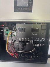
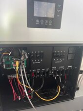
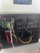
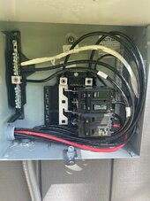
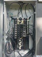
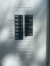
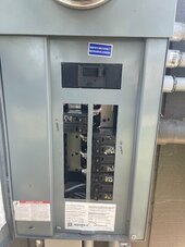
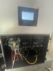
Hope everyone is doing well. Below are the photos of the combiner box and sub panel. Here are the issues that we are having.

When we first installed the system we just powered up inverter number 2 it was attached to the battery and was charging it perfectly and pulling good numbers from the PV. Then we installed PV1 and installed the combiner box and the powered up the loads. The inverters would kick on one at a time to power the loads up to 12kwh and then would short out and then the other one would kick on and go all the way up to 12kwh and then short out.

Now inverter 1 is running perfectly but if I throw the loads breaker on inverter 2 it shorts the whole system out and shuts off power to the house. Then if i put inverter 1 in standby and turn on inverter 2 loads nothing happens at all no PV to loads and no PV to battery only about 100w is trickling into the battery.

  1. Dongles won't connect to server
    1. reset dongles
    2. all three lights come on when local connected and stays on after but does not show online on the internet
  2. Inverter #2 will not produce PV power only 100w at a time to charge the battery when over 30 panels are connected to it
    1. This was the first inverter installed and was functioning fully when we first installed the system and now will not power any loads
    2. when the load breaker is switched from OFF to ON it shorts out inverter number 1 and it shuts off power to the whole house until I turn OFF loads on number 2 and then restart inverter 1 .
  3. 3. When in parallel neither inverter works.

I think there is a short in inverter 2 that is causing the other inverter to short when the loads are on.

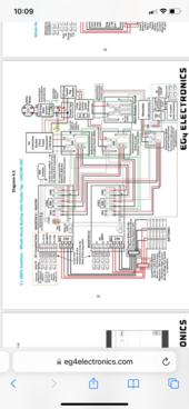
      If there are any suggestions or If I don't have the combiner box wired right please let me know. thank you!
 

Attachments

  • IMG_1292.jpg
    IMG_1292.jpg
    57.4 KB · Views: 41
  • IMG_1293.jpg
    IMG_1293.jpg
    51.4 KB · Views: 42
  • IMG_1294.jpg
    IMG_1294.jpg
    34.3 KB · Views: 31
  • IMG_1295.jpg
    IMG_1295.jpg
    35 KB · Views: 38
  • IMG_1296.jpg
    IMG_1296.jpg
    53.3 KB · Views: 39
  • IMG_1297.jpg
    IMG_1297.jpg
    64.3 KB · Views: 35
  • IMG_1298.jpg
    IMG_1298.jpg
    79.2 KB · Views: 35
  • IMG_1300.jpg
    IMG_1300.jpg
    37.1 KB · Views: 35
  • IMG_1301.jpg
    IMG_1301.jpg
    49.1 KB · Views: 39
Is your battery cable welding wire? Is this the wiring diagram you used?
 

Attachments

  • IMG_5091.png
    IMG_5091.png
    372.1 KB · Views: 7
Last edited:
I can’t tell from the pictures but I’d have to guess your grid and/or load phasing is reversed between inverters. Hopesully you haven’t done any damage
 
I see so many problems here, the wiring is a mess and under rated.
The inverters cannot run ok up to 12kw and then "short out"....my guess is they try to switch to bypass and the phases are mixed up.
 
 
In picture 2 if they're not just set aside for now, the panel manufacturer will sell blanking plates to fill in all the empty spaces on the panel cover.
 
Trace all ac wires down load and grid, and label each end L1 or L2. If any are crossed you will have big problems. If you don’t understand you can have an electrician go over it. You could also turn off all breakers and do a continuity test between L1 and L2. You should have no continuity between them.
 
You need to talk to your electrician if this is the 200A service you were talking about in another thread:
“Panels are already installed. but yes we are going to hire him and do the job properly.”
I don’t see “properly” anywhere in there…
 
You need to talk to your electrician if this is the 200A service you were talking about in another thread:
“Panels are already installed. but yes we are going to hire him and do the job properly.”
I don’t see “properly” anywhere in there…
Could not agree more.
 
For the Wi-Fi dongle, I would recommend connecting to a 2.4ghz network and ensuring that auto-negotiate is disabled on the router. Having the router set to WPA2 also helps with connectivity. If the dongle will not connect after this, I would try following the document attached to this post. For the two inverters not paralleling, I would recommend connecting the paralleling cable as highlighted below and ensuring that the gray full pinout communication cable is being used.

1711120512099.png
 

Attachments

  • EG418Kpv-How to recover a dongle if Restore factory setting (1) (2).pdf
    479.9 KB · Views: 0
no we have the inverters each on its own 60 amp output in a 150amp AC combiner box to the 200 amp subpanel
Wow,

Man, I'd rethink your wiring setup a bit.

I'd start by getting black/red jacketed conductors for L1/L2 for sanity. Banding is OK, but #6 wire is not that expensive, and you can't screw it up if it's the whole jacket. I can't make out the displays, but this looks a little hap-hazard. I've been running in parallel since I installed, Verify the units are talking and in-phase before you energize anything. I would also make sure I'm connected with a phone/tablet to the Wifi Dongles, and get all the firmware up-to-date. You basically must swap the phone's Wifi back and forth.

These are mine . . .

1711135403031.png

1711135447300.png

I can't make these out from your pics, and you didn't show your settings screens Based on this picture . . .

1711135554773.png

I don't see the Inverter-Inverter communication cable connected. It would be here (my pic)

1711135687900.png


Further, you have a standard patch cord in the battery comm port. This means you either made a mistake or you are doing something custom, to a custom set of batteries. Provided cable peels out RS-485.

I mean this is just at a glance. . . You may want to start over from the top and get things in order one at a time, tracing wires and such . . . Feel free to step thru on this thread, maybe we can catch the problem.
 
Update:

Got them in parallel right now, only one inverter is getting PV will repatch the 3/ot gauge battery wire so at least can see if inverter number 2 will charge without a battery open issue. Will update Monday. Also got the Dongles to connect to the web. Below are the connections photos.
 
This is DIY right ? Learning to do it DIY
No one is perfect or knows everything. When I take on an unfamiliar DIY I usually study it for at least a couple weeks. This is to get a good understanding of the project before way too much money is spent I especially take note of the manner in which other people accomplish the same thing. I then find out for myself why it was done that way. In doing that step, I usually find out what the significant steps are for ensuring safety of the system or person dependent on the DIY job. It seems my DIY is not the same as other peoples.
 
So there is a "shared battery" setting, but both of your inverters should be connected to batteries. I would start by having all the batteries on a shared bus in parallel to both inverters and just have the primary manage it, turn on the shared battery setting. Start as simple as possible.

If you haven't already, ... Seriously, you should start with a firmware upgrade and get the inverters online, They are much easier to manage.

What kind of batteries do you have? Your yellow patch would seem to indicate CAN bus to a 3rd party or something.
 
I only see one of the two inverters above. If you only have TWO inverters you only need 1 parallel cable. Not sure what the other loose grey is coming out the door in parallel #2. Dip swtches: UP on primary down on secondary. Put both in the first/left hole. If you add a 3rd inverter you will want to daisy chain. The parallel cable is straight thru, any patch will work.

All the AC connections need to be bussed. You really don't need a combiner box, Fine f your paranoid, but a small bus-bar is simpler. I ran #2 from the panel to 3 different bus bars, then #4 from each of the inverters to each of the bus bars (I had it, #6 is fine). My bus bars are black/red/black and all the cable is black/red/white. Couldn't find a 100A white bus bar, but at a glance it's obvious which phase/neutral is which. Internally the inverters will limited to ~50A to load, before it shuts down.
 
Back
Top