diy solar

diy solar

EG4 6000EX - Double Ground/Neutral

My understanding is he disconnected the AC input from the main panel. The small panel supplied by the inverter is still connected.

Maybe I'm reading wrong but that was my take on the situation.


That is what my thinking is, if the bonded small panel is connected to AC output which I understand to be the case. If the small panel is connected and bonded and the inverter is bonding N-G, then he has 2 bonds.

Again, my understanding is the small panel is connected.


I'd rather determine what is connected and disconnected before moving on to a solution. I'd prefer an earth reference no matter what with an EGC from the service panel to the inverter connected.

You have a good point there. :)

I have no AC input. Just "for now" only have 8 36v panels (280w), EG4 3kW 120V inverter and two 5kW lithium batteries.

According to tech at SigSolar he told me after I did continuity test over phone with him the neutral & bond were connected in AIO.

When I first checked inverter with battery on, but AIO in off position there was no continuity. After turning the AIO on, I got continuity.


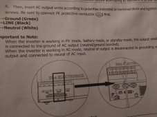
There is a note in manual that says "When the inverter is working in PV mode, battery mode or standby mode, the output neutral is connected to the ground of AC output (neutral/ground bonded).

When the inverter is working in AC mode, neutral of output is disconnected to grounding of AC output and connected to neutral of AC input."

See attached pic.

My understanding from phone call the bonding "somehow discoonects" when connected to AC input
 

Attachments

  • IMG_20230130_211347901.jpg
    IMG_20230130_211347901.jpg
    171.7 KB · Views: 13
According to tech at SigSolar he told me after I did continuity test over phone with him the neutral & bond were connected in AIO.

When I first checked inverter with battery on, but AIO in off position there was no continuity. After turning the AIO on, I got continuity.
The fact that you had no continuity when the inverter is off tells me the screw is not there. The fact that you saw 62V between neutral and ground on the output tells me the screw is not there. What is the manufacture date of the unit?

Measuring continuity with the unit on is a bogus test. The voltage from the inverter will confuse the ohmmeter. (It is *really* sad the sig solar techs are so poorly trained that they don't know this)


An ohm meter or a continuity tester works by putting a voltage accross the two points and measuring the current.

This is a simple schematic of an ohmmeter

1675133175999.png


Now lets put 120V AC on it.


1675133532065.png

The 120V is going to make any measurment by the ohmmeter completely bogus.
 
The fact that you had no continuity when the inverter is off tells me the screw is not there. The fact that you saw 62V between neutral and ground on the output tells me the screw is not there. What is the manufacture date of the unit?

Measuring continuity with the unit on is a bogus test. The voltage from the inverter will confuse the ohmmeter. (It is *really* sad the sig solar techs are so poorly trained that they don't know this)


An ohm meter or a continuity tester works by putting a voltage accross the two points and measuring the current.

This is a simple schematic of an ohmmeter

View attachment 132351


Now lets put 120V AC on it.


View attachment 132352

The 120V is going to make any measurment by the ohmmeter completely bogus.

It's a fairly new inverter. It's the newer model (second version) I purchased it in late November.

I thought I read posts where they were not putting in ground screw in them anymore.


Here is a link on YouTube where guy says you need to add bonding screw for his camper

 
Yes, they made that change without telling anyone sometime in Q4 of last year.

So user ZWY says my unit is N-G bonded, but you say it isn't. And Sig Solar tech told me it was after I did the continuity test.

You can see how easy it is to get confused.

EDIT
After re-read I g user ZWY posts, I think he concurs with you, that it is not bonded in battery/ inverter mode.
 
Last edited:
So user ZWY says my unit is N-G bonded, but you say it isn't. And Sig Solar tech told me it was after I did the continuity test.

You can see how easy it is to get confused.
Yes, I see how you could be confused and I don't know how to advise you on who to believe. All I can do is give my reasoning for why I think the other opinions are incorrect and why I think the screw is not there.

* Sig solar had you do a bogus test. (See explanation above)
* @Zwy believes you measured the 62V when the inverter output was hooked to the small distribution box with the N-G bond. (How you would see 62V across an NG bond is beyond me)

Meanwhile, you reported three things that, in my opinion, clearly indicate there is no bonding screw:
1) 62V across the output neutral and the ground is a clear indication that there is no bond and therefore no bonding screw. If there was a bond between Neutral and ground, the voltage would have to be close to zero.
2) Every inverter that does dynamic bonding that I have worked with uses the Normally-Closed position of the bonding relay for the bond. This means that if the inverter is off, the relay is in the bonding-on state. You measured continuity with the inverter off and saw no continuity. This indicates the screw has been removed.
3) You have a new unit and EG4 has said they are now shipping all models without the bonding screw.

Thanks.

I had hoped at some point to feed my inverter when batteries got low in my off-grid setup from an outlet from house, but will refrain from doing that with the bonding issues.

Thanks again.
 
So user ZWY says my unit is N-G bonded, but you say it isn't. And Sig Solar tech told me it was after I did the continuity test.

You can see how easy it is to get confused.

EDIT
After re-read I g user ZWY posts, I think he concurs with you, that it is not bonded in battery/ inverter mode.
One question, is the N-G bonded small panel connected to the inverter output?

As for whether the inverter is dynamically bonded, I agree with @FilterGuy. Why is there 62V between N and G at the inverter? If the small panel is connected and N-G bonded and the inverter is not, my assumption is 1/2 the current is traveling back to the inverter (source) on G. Which can only be possible with some type of path inside the inverter. Maybe the unit is defective, something just doesn't seem right.

If the small panel isn't connected during testing, then ignore all the above.
 
It seems the problem is between bypass through mode (ACIN) and inverter mode. In bypass, NG is bonded back in the main panel via the EG's ACINput. Thus there would be 2x NG bonds with the NG bond in the critical load box. In inverter mode, ACOUT-N is float and thus needs the NG bond in the critical load panel. I guess you can implement a relay to dynamically NG bond in your critical load box: unbond while in bypass-mode and bond in inverter mode....but where's the trigger signal ? is there an ON/OFF switch ?
 
One question, is the N-G bonded small panel connected to the inverter output?

As for whether the inverter is dynamically bonded, I agree with @FilterGuy. Why is there 62V between N and G at the inverter? If the small panel is connected and N-G bonded and the inverter is not, my assumption is 1/2 the current is traveling back to the inverter (source) on G. Which can only be possible with some type of path inside the inverter. Maybe the unit is defective, something just doesn't seem right.

If the small panel isn't connected during testing, then ignore all the above.

You can test the above if the OP has a clamp meter. If half the current is returning to ground we will see it.
 
One question, is the N-G bonded small panel connected to the inverter output?

As for whether the inverter is dynamically bonded, I agree with @FilterGuy. Why is there 62V between N and G at the inverter? If the small panel is connected and N-G bonded and the inverter is not, my assumption is 1/2 the current is traveling back to the inverter (source) on G. Which can only be possible with some type of path inside the inverter. Maybe the unit is defective, something just doesn't seem right.

If the small panel isn't connected during testing, then ignore all the above.

The N-G is bonded in my small panel that is fed from my inverter. When i did the test that FilterGuy recomended I disconected everything from the AC out on the inverter (ground, neutral, hot). The only thing connected to the inverter when i did my test was the battery cables. I beleive i had my solar PV disconnected when i did the test.
 
The N-G is bonded in my small panel that is fed from my inverter. When i did the test that FilterGuy recomended I disconected everything from the AC out on the inverter (ground, neutral, hot). The only thing connected to the inverter when i did my test was the battery cables. I beleive i had my solar PV disconnected when i did the test.
Thank you, yes, the inverter is not bonding N-G.
 
OK!!! Thank you for the video and the fix EG4/Sig Solar. This is a huge improvement! Up till yesterday, I was under the impression the relays in the internal transfer switch were not individually addressable. The fact that they are addressable is a game changer.

* With the new firmware, the system operates as a common neutral and that works well for most (All?) stationary systems.
* For mobile solutions, the 'mobile' firmware that uses the bonding relay will work well in most cases (See limits below).

An important question:
When will this all be documented in the manual?

A question to satisfy my curiosity:
Why not put a new 'program' in the firmware that allows the user to select common neutral vs mobile? Was the solution done to get it out quickly with a plan for a configurable firmware solution coming later?

A question about shipping with the bonding screw.
If the relays are individually addressable, the new firmware can be set up to not engage the bonding relay. Therefore the bond would not be created even if the bonding screw is in place. Why not do this and go back to shipping with the screws so the mobile user does not have to source his own screw and open the inverter to install it?

Finally, there are some limitations for the mobile Firmware that should be noted

Stacking inverters:
* With the common neutral firmware, the bonding relays are not used and therefore the relays do not impose a limit on stacking (There may be other limits though)
* With the mobile firmware, The only stacking that should be done is two inverters in split phase mode. Two in parallel mode or more than two inverters in any mode create a situation where the bonding relay is undersized.
* With the mobile firmware, The bonding screw in one of the inverters should be removed.
NOTE: Hopefully you can make this configurable in a future version of the firmware... better yet, when the mobile firmware is operating, only enable the dynamic bonding on the master inverter and not on the other inverter.​

Non-Neutral-switching transfer switches on the output.
* With the common neutral firmware, a non-neutral switching transfer switch on the inverter output will work fine. This means the Reliant multi-circuit transfer switch is OK to use.
* With the mobile firmware, a non-neutral-switching transfer switch could create two bonds when on battery power and therefore should not be used.
 
Super helpful. I'm doing a mobile project with (2) EG4 6500EX-48's in "split phase" (240V).
My inverters were ordered 2/2023. Based on what I've learned here:
  • I need to install the "mobile firmware" via https://eg4electronics.com/downloads/
  • Install a M2.5 x 10mm bonding screw in ONE of the inverters.
  • Main panel (inverter output) - neutral and ground are NOT bonded.

Let me know
 
I would still check to confirm NG bonding as expected after installation, may be that's already obvious.
 
Hello Folks,

Has anyone remove the neutral-ground screw from the eg4 6000 ex, and possibly have the lactation or pictures of where it is located?

Thanks
 
Folks, I describe the grounding/bonding of the 6000 in this post:
 

diy solar

diy solar
Back
Top