diy solar

diy solar

EG4 6500ex-48 to 30amp or 50 amp transfer switch?

RickRoades

New Member
Joined
Feb 22, 2023
Messages
19
Location
Oklahoma
I’m new so my logic is likely not complete or sound, advice welcomed. I purchased the EG4 6500EX-48 and 1 EG4 LL battery, for now. Staged goals are based having a portable dual fuel generator w/ propane (1000 gal tank) and hook up
  1. Power outage back up for food refrigeration (Several), some lights and computers for work, extension cords at first. Recharge battery with generator using Chargeverter, extending fuel and coverage for the outages, no solar panels yet.
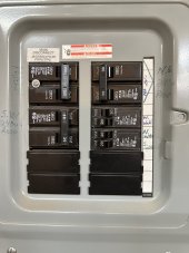
  2. Added convenience in outages, using a manual transfer switch from battery -> switch -> main, leaving on Line until the outage, still no solar panels
  3. solar panels will be last as have yet to find best place for a ground mount while hoping not to advertise having them. Will likely involve dozer/landscaping etc.
My questions and thoughts:
Transfer switch, 10 circuit?plan to add 2nd EG4 6500ex240v lower priority
50 or 30 amp Cord and plug?1 EG4 = 120v, 50 amp switch is 240v plugUse this with only wired for 120v?
6500ex can do 50 ampsunderstood that battery would drain quickly, but the point is to not have to rewire in the future beyond adding the inverter or more batteries, and don’t intend to pull 50 amps, just thinking about capability
Cutting electric grid usageWith solarrun daytime circuits on battery/inverterNight time on LINE as needed
With solar and additional batteriesRun some circuits more permanentlyCan still charge with generator
Added inverter to aboveRun AC and/or most on solar
Take it with me if we movenothing permanently installedSwitch is easy, just unhook from panelSolar panels stable mount but not permanent, possibly something like the EG4 ground mounts

What don’t I know?

Thanks in advance.
Rick
 
If you wanted flexibility for future growth, it might be worth looking at a separate sub-panel (critical loads panel) and you put a manual transfer switch between the inverter and the CL panel. Then you can add X number of circuits to that panel down the road as you grow your system.

I just added a manual transfer switch to my setup and wished I would have done it from the beginning. Makes things so much simpler when I have to service the system.

Edit: Like you said though, I would size up larger than you need right now in order to prevent the need from changing down the road. I thought the manual recommended a 60a breaker as these inverters can output 54a AC. You could use a double pole 60a breaker and only use the one leg for now.
Thanks for the help! When I moved in, I had a sub panel installed on a 100 amp breaker for my garage wood shop, currently 2 double pole for 2 240v receptacles, 3 20amp for outlets on 3 walls. Pic attached. I’m only just understanding home electrical, and it’s always scared me ?. But I’ll probably hire it out. I could add CL to that panel, as the main panel is hidden in a garage closet behind the water heater. Good advice on the 60 amp breaker, I wasn’t sure how that would work. As for inverter to manual transfer switch, is it best to go to a bus bar now, then 60a breaker, then to 50a receptacle, lastly to the switch so if/when I add the next inverter I just add to the bus bar, engage the other leg? Haven’t looked at that part yet, but guess I should before I commit. My eyes glaze over!?

one other quick question on the LL battery - it’s hooked straight to the inverter like Will Prowse shows for a simple back up but with inverter off, unplugged from mains, battery breaker off and battery off, I’m showing 2+ volts across the battery terminals. I realize that‘s pretty low, but shouldn’t it be 0?
 

Attachments

  • IMG_6485.jpeg
    IMG_6485.jpeg
    141.3 KB · Views: 7
The bus bars are on the DC side of things. The AC side should have a breaker pretty close to the output of the inverter. You can have a double pole breaker and only use the one side right not for the single inverter.

The transfer switch has 2 inputs and 1 output. One input will be the grid connection, the other input is the AC Out from the inverter. The output of transfer switch goes into the 60a breaker on the CL panel. At least that’s how I have mine wired up.

As far as the battery voltage, sometimes it’s just latent voltage from the BMS in the battery, sometimes it’s an incorrect reading from your meter. Either way voltage that low is really nothing to worry about. I still would make sure you don’t accidentally bridge the positive and negative together though….?
 
Back
Top