diy solar

diy solar

EG4 Brightmount and Permitting

Seems like there will be a lot of stress on the joints of the EG4 mount, at 105 mph. Especially at the 5"x5" mounting plate. Thoughts?
I thought the same. Noticeably absent from analysis doc, though what Jarrett posted is appreciated (also note maximum size panels analyzed, most of us will have smaller). I figure county mounties may show up at some point so planning ahead. Kinda crazy but concrete is cheap?? Note those are standard 48" sonotubes so "only" 30 inches in ground (24" frost depth here) .
20231206_133927.jpg
 
I thought the same. Noticeably absent from analysis doc, though what Jarrett posted is appreciated (also note maximum size panels analyzed, most of us will have smaller). I figure county mounties may show up at some point so planning ahead. Kinda crazy but concrete is cheap?? Note those are standard 48" sonotubes so "only" 30 inches in ground (24" frost depth here) .
View attachment 187714
We probably over did it, but we used 54" sonotubes, to get to 36" depth for frost, with 18" above.
 
In So Cal we have no frost, so 36 inch sonotubes here, 30 inches into the ground. The advantage of using schedule 40 2" galvanized pipes and crossmembers as well as Superstrut is that you can engineer the exact placement of the cement tubes, ie front to back distance of posts and distance between posts in a row. Pipe comes in 20 foot lengths. Just figure out what panels you are mounting and how many in what orientation and the software tells you exactly the number of posts to place in the ground and the distances between them. Then connect all with Hollaender Tee's and voila, a perfect array, properly spaced. Here's a couple of examples.
 

Attachments

  • mount 5-1.jpg
    mount 5-1.jpg
    472.7 KB · Views: 24
  • mount 13-1.jpg
    mount 13-1.jpg
    497.7 KB · Views: 24
I thought the same. Noticeably absent from analysis doc, though what Jarrett posted is appreciated (also note maximum size panels analyzed, most of us will have smaller). I figure county mounties may show up at some point so planning ahead. Kinda crazy but concrete is cheap?? Note those are standard 48" sonotubes so "only" 30 inches in ground (24" frost depth here) .
View attachment 187714
Technically speaking, the cement finish on the top of the sonotube is supposed to be highest in contact with the metal if inserting a post. In this case, from the photo, it appears that the posts are bolted into the concrete of the sonotube and nothing else is inserted into the cement? If that's right, then the sonotubes serve only as ballast against wind loading as well as some added height from the ground. Unless the bolts are stainless steel, they will corrode over time from lime in the cement. Nothing you can do about that. However, since water may pool on the top surface of the sonotube, you may wish to apply a waterproof coating to the cement and metal to help prevent corrosion. Drainage is the best solution.

When inserting a metal post into cement, best practice is to wrap the post in 10 ml PVC tape to prevent direct contact of the cement (which contains lime) with the metal to prevent corrosion over time.
 
In this case, from the photo, it appears that the posts are bolted into the concrete of the sonotube and nothing else is inserted into the cement? If that's right, then the sonotubes serve only as ballast against wind loading as well as some added height from the ground
Yes, that's why we are questioning that joint, especially per the original design reacting the giant moment from the panels thru the single 5×5 joint. That's why I added the front support to cancel the moment. I used the 12 inch sonotubes partly because I'm lazy getting holes chalklined / lined up ( :) :ROFLMAO:) but, more importantly, each tube weighs 500 lbs x 2 = 1000 lbs same as the one giant cube original design calls for (ballast for wind load, agree with you). Also, if someone one day wanted to REMOVE them something simple like my tractor loader will pick them up easy.

Concrete anchors are stainless steel as you suggest, thx.

I'm 99.9% sure my County would look at those and say OK, wave off structural PE. If they require PE I'm 99.99999% sure they'll pass and ask a Civil PE friend to sign or Greenlancer.
 
Last edited:
Because of our ground components, we were able to dig the 36 inches in some spots and install the schedule 40 2 inch pipes into the concrete. We purchased a concrete mixer from Lowe's (same one at HD, the orange one) and easily poured the 4 corners of the array. Plumbing these posts is real easy and shaping the top for drainage is very simple. This is an excellent source of ballast.

Where we were unable to sink the sonotubes due to granite formations, we built the 24x24x24 inch concrete blocks, steel reinforced at the direction of a structural engineer and permitted and then proceeded to set the posts.

Once the 4 corners of your array are poured and set for a day, you can use a survey or line string tied around the 4 corners and then simply pour all of the in between posts and plumb them to barely make contact with the string. This puts them all in alignment. After another day, use the string from front row to back row on the left and right ends of the array. Adjust the height to set your angle. Mark and cut off the tops of the posts. Now run the string across left to right for the front row and another for the back row, mark and cut of the remaining tops of the posts. Now you should be left with a front row of shorter posts and taller posts in the back row. All posts in a row should be the same height. Place your tee connectors on the post tops, pass the horizontal row posts through the tees and fasten them into place. Do this for each row and use connectors if your array is wider than 20 feet. Then place Superstruts or any other solar rails you want across the horitzontal rails. Cut a couple of 2x4 to the correct width between the Superstruts needed to mount your panels. Set the first strut in place, use the 2x4s to set the next strut parallel and spaced from the first into place and so on and so forth until all struts in place. Then start mounting your panels.
 
Interesting. So you need 4 concrete mounts per rack, each ~20” wide and ~34” deep to meet a 105mph wind speed rating.

Super quick math is ~6 Cu ft of concrete * 4 posts is 24 Cu Ft or 3600 lbs of concrete total.

So just shy of a cubic yard per rack. That's a lot of concrete and cost.
 
Assume those plans and following that spec for concrete/mounting will pass an inspection though if you are in a 105mph zone.

Oh absolutely, just the cost advantage starts to go away compared to other racking when you're talking about that much concrete + excavation for said concrete. For 4 or 8 panels, sure the Brightmount is great, but if you're looking into 30+ panels, I don't think I'd go that route now. I'd probably look at a ground screw mount for slightly more money, just due to the labor involved in that much concrete.
 
Oh absolutely, just the cost advantage starts to go away compared to other racking when you're talking about that much concrete + excavation for said concrete. For 4 or 8 panels, sure the Brightmount is great, but if you're looking into 30+ panels, I don't think I'd go that route now. I'd probably look at a ground screw mount for slightly more money, just due to the labor involved in that much concrete.
@kscessnadriver Any recommondations for ground ground screw mounts, low to the ground like the brightmounts?
 
@kscessnadriver Any recommondations for ground ground screw mounts, low to the ground like the brightmounts?

None really, I was looking into the APA Ready Rack, but it's not a low profile mount like a Brightmount. Of course you could go with a ballast mount, like Powerfield's Powerrack, but that's a whole different discussion.
 
None really, I was looking into the APA Ready Rack, but it's not a low profile mount like a Brightmount. Of course you could go with a ballast mount, like Powerfield's Powerrack, but that's a whole different discussion.
Yeah, was looking at those also.
 
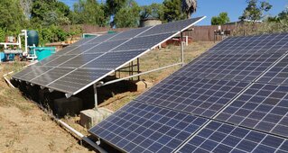
I posted these elsewhere I think on the forum. Anyways, sola tubes, 12 inches in diameter to the depth you need is simple to set, fill and plumb your post.

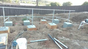
If you cannot dig deep due to ground conditions, then the 2 blocks you see were built at direction of structural engineer:

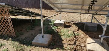
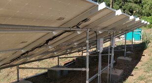
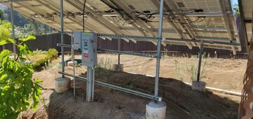
They measure 24x24x24 inch cubes. They are built out of the cheapest panels you can get and nailed at the corners. The insides were sprayed before pouring with vegetable oil for easy release. The cube is set into the ground about 6-12 inches so it does not slide when poured. The inside volume of the cube is steel reinforced by building a rebar frame of approximately 16x16x14 inches just connected together with the concrete wire ties. Then the rebar frame is held off the ground by the small concrete rebar blocks or even a piece of brick. Your array post is set in the center of the empty block with the rebar. The post has a small piece of strut like 6 inches u-bolted to it so it will not ever rotate in the concrete.

Once all your forms have been made and string aligned, pour the four corner blocks and align and plumb up your posts. Each block will require 10 bags of concrete, 100 lbs each and final weight between 1000-1100 pounds each. I suggest you purchase or rent a small concrete mixer and each pour is maybe 45 minutes to an hour.

Every post you add to the array adds 1000 -1100 of ballast.

To build the forms, each 4 x 8 panel will can be cut into 8 pieces and will make 2 4 sided forms. They can be reused, but in our case the inspector wanted to see all forms in place with rebar prior to pouring.

When pouring the forms, strike the sides of the forms with a rubber mallet or 3 lb mallet to remove air pockets and settle the concrete in the forms.

This method is a little labor intensive compared to sola tubes, but it works and is not complicated. And i can tell you after 8 years it performs well, but we have no freezing weather.

If pouring, make certain to angle the top of cubes so water drains away on all 4 sides of the top from the post.
 

Attachments

  • mount 1-1.jpg
    mount 1-1.jpg
    577.6 KB · Views: 9
  • mount 2-1.jpg
    mount 2-1.jpg
    484.2 KB · Views: 9
  • mount 3-1.jpg
    mount 3-1.jpg
    450.8 KB · Views: 9
  • mount 5-1.jpg
    mount 5-1.jpg
    470.3 KB · Views: 9
Back
Top