After reviewing "Electrodacus-based system schematic (final version w detail)", I thought about system that I was design for my van. I was wondering if I could use Electrodacus in my design. Please review my design. Did I miss anything or is there a problem? Thanks for you input!


You are using an out of date browser. It may not display this or other websites correctly.
You should upgrade or use an alternative browser.
You should upgrade or use an alternative browser.
Electrodacus Design-Adding Alternator and Inverter/Charger
- Thread starter APhoton
- Start date
Nice schematic, I get the feeling this ain't your first. Very clean.After reviewing "Electrodacus-based system schematic (final version w detail)", I thought about system that I was design for my van. I was wondering if I could use Electrodacus in my design. Please review my design. Did I miss anything or is there a problem? Thanks for you input!
I have only looked at it very briefly so far.
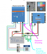
One thing that jumped out at me is there is no grounding pictured in the diagram (other than on the AC side between the inverter and load center/loads).
Thanks, I'm retired so I have a lot of time-lol! I did another diagram with a Daly BMS before I thought about the Electrodacus. I am very much a newbie so please excuse any crazy ideas.
I do have ground from negative busbar to chassis. This is for a RV. Should I ground each component?
Inverter/Charger?
Solar Panels?
?
Victron DC-DC 12/24 charger-No because it is isolated?
grounding and how to accomplish was something I debated
I do have ground from negative busbar to chassis. This is for a RV. Should I ground each component?
Inverter/Charger?
Solar Panels?
?
Victron DC-DC 12/24 charger-No because it is isolated?
grounding and how to accomplish was something I debated
One thing that applies to everything I say about grounding and safety. I am not an expert (not even solidly intermediate), I have a limited understanding of electrical theory and grounding theory, I am certainly still learning and probably misunderstand a thing or two. Bearing that in mind, here are my thoughts:
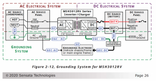
My understanding of the semi-default (there is no default you need to make sure whatever you do works for your situation) grounding logic is that all EGC's (equipment ground conductors--the wires between the metal non current carrying parts of your components and your system ground point) go to one central point which is than bonded to DC negative and(or) Chassis ground (see attached image).
There is slightly more complexity with an inverter charger, because it needs to internally switch the ground depending on whether shorepower is connected or not. And of course I have only touched on the DC side of things, I won't comment on the AC side because I am not knowledgeable enough and it scares me ?
SCC can also optionally be grounded (in the same way as you ground the inverter/charger to the negative bus).
I would say a good way to start learning is to really pour over some of the schematics put out by reputable companies (such as the Victron one I posted earlier). And check out some of the Inverter/Charger manuals they have sections on grounding as it pertains to mobile/marine systems. Samlex and Magnum would be two I recommend peaking at. Also check out the free Victron E-Book Wiring Unlimited and the ABYC guidelines (this is Marine code, but super useful for vehicle based builds too)
Oops sorry, I missed that, was looking out for green wire or a ground symbol.I do have ground from negative busbar to chassis.
At the very least the Inverter should be grounded in accordance with the manufacturer recommendations which probably means bonding the inverter case to the negative busbar.This is for a RV. Should I ground each component? Inverter/Charger?
My understanding of the semi-default (there is no default you need to make sure whatever you do works for your situation) grounding logic is that all EGC's (equipment ground conductors--the wires between the metal non current carrying parts of your components and your system ground point) go to one central point which is than bonded to DC negative and(or) Chassis ground (see attached image).
There is slightly more complexity with an inverter charger, because it needs to internally switch the ground depending on whether shorepower is connected or not. And of course I have only touched on the DC side of things, I won't comment on the AC side because I am not knowledgeable enough and it scares me ?
It is my understanding that it is recommended (however your PV panels may be grounded by default if you use metal fasteners to connect the metal frames to a metal roof (or metal ribs).Solar Panels?
If both sides of your system are grounded then your DC-DC charger will not be isolated regardless of whether you buy the isolated or non-isolated version because the negative sides of both systems are bonded together via chassis-ground. Regarding grounding, if memory serves, Victron does not stipulate grounding for the DC-DC charger.Victron DC-DC 12/24 charger-No because it is isolated?
SCC can also optionally be grounded (in the same way as you ground the inverter/charger to the negative bus).
In my opinion this is one of the hardest aspects of a mobile built (with multiple charge sources) to wrap your head around. I am still struggling to really understand it and feel confident in my understanding. But slowly, I'm starting to get there.grounding and how to accomplish was something I debated
I would say a good way to start learning is to really pour over some of the schematics put out by reputable companies (such as the Victron one I posted earlier). And check out some of the Inverter/Charger manuals they have sections on grounding as it pertains to mobile/marine systems. Samlex and Magnum would be two I recommend peaking at. Also check out the free Victron E-Book Wiring Unlimited and the ABYC guidelines (this is Marine code, but super useful for vehicle based builds too)
Attachments
Thanks Dzi, great informationOne thing that applies to everything I say about grounding and safety. I am not an expert (not even solidly intermediate), I have a limited understanding of electrical theory and grounding theory, I am certainly still learning and probably misunderstand a thing or two. Bearing that in mind, here are my thoughts:
Oops sorry, I missed that, was looking out for green wire or a ground symbol.
At the very least the Inverter should be grounded in accordance with the manufacturer recommendations which probably means bonding the inverter case to the negative busbar.
My understanding of the semi-default (there is no default you need to make sure whatever you do works for your situation) grounding logic is that all EGC's (equipment ground conductors--the wires between the metal non current carrying parts of your components and your system ground point) go to one central point which is than bonded to DC negative and(or) Chassis ground (see attached image).
There is slightly more complexity with an inverter charger, because it needs to internally switch the ground depending on whether shorepower is connected or not. And of course I have only touched on the DC side of things, I won't comment on the AC side because I am not knowledgeable enough and it scares me ?
It is my understanding that it is recommended (however your PV panels may be grounded by default if you use metal fasteners to connect the metal frames to a metal roof (or metal ribs).
If both sides of your system are grounded then your DC-DC charger will not be isolated regardless of whether you buy the isolated or non-isolated version because the negative sides of both systems are bonded together via chassis-ground. Regarding grounding, if memory serves, Victron does not stipulate grounding for the DC-DC charger.
SCC can also optionally be grounded (in the same way as you ground the inverter/charger to the negative bus).
In my opinion this is one of the hardest aspects of a mobile built (with multiple charge sources) to wrap your head around. I am still struggling to really understand it and feel confident in my understanding. But slowly, I'm starting to get there.
I would say a good way to start learning is to really pour over some of the schematics put out by reputable companies (such as the Victron one I posted earlier). And check out some of the Inverter/Charger manuals they have sections on grounding as it pertains to mobile/marine systems. Samlex and Magnum would be two I recommend peaking at. Also check out the free Victron E-Book Wiring Unlimited and the ABYC guidelines (this is Marine code, but super useful for vehicle based builds too)
I have discovered an issue.
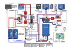
1. SBMS0 needs to have two connection to inverter/charger- one for the inverter controlled by SBMS0 EXT IO3 set as type 2 and the other for the charger part that will need to be separately controlled by EXT IO4 set as type 1. Sun Gold Power only has one remote input for inverter. I will need to install solid state relay on AC side to control charger when connected to shore power.
2. I have used all 4 of the EXT IOx so I will need branch EXT IO4 with optoisolators in order to control shore power charge sources.
Issue is that this is starting or is over my pay scale! I have no idea or am not exactly sure how to select size or wire in either Solid State Relay and/or optoisolators. I have attached drawing of what I think is correct?
Also, back to ground I added grounding wires and SBMS0 wiring to my drawing
Attachments
Last edited:
Yeah, I figured that would be the case with the SunGoldPower inverter but I wasn't positive.Thanks Dzi, great information
I have discovered an issue.
1. SBMS0 needs to have two connection to inverter/charger- one for the inverter controlled by SBMS0 EXT IO3 set as type 2 and the other for the charger part that will need to be separately controlled by EXT IO4 set as type 1. Sun Gold Power only has one remote input for inverter. I will need to install solid state relay on AC side to control charger when connected to shore power.
Above my pay grade as wellIssue is that this is starting or is over my pay scale! I have no idea or am not exactly sure how to select size or wire in either Solid State Relay and/or optoisolators. I have attached drawing of what I think is correct?
") Good luck. There are people here with a good bit of insight into using optoisolators, and if you can't get your question answered here, Dacian's message board could probably help
Good luck. There are people here with a good bit of insight into using optoisolators, and if you can't get your question answered here, Dacian's message board could probably helpI will see if I can find something on Electrodacus forum also that is where I got drawing which I think will work but they were not doing exactly what I want. One though was to think about a different inverter/charger???
Thanks for all your help!
Thanks for all your help!
The Victron Multiplus 3000 is what most people seem to use, you can control inverting and charging separately. Alternatively you could get a simple inverter and a standalone charger like the meanwell RSP-750-27 (this may be cheaper)I will see if I can find something on Electrodacus forum also that is where I got drawing which I think will work but they were not doing exactly what I want. One though was to think about a different inverter/charger???
Thanks for all your help!
I just thought of something if I where to add a solid state relay on AC side so so when any cell is full the SBMS0 can just disconnect the grid and thus stop the charging. That great for the battery but if I'm in a campsite plugged into grid so that I can use grid electricity then that's not so great! Am I missing something??The Victron Multiplus 3000 is what most people seem to use, you can control inverting and charging separately. Alternatively you could get a simple inverter and a standalone charger like the meanwell RSP-750-27 (this may be cheaper)
I think for this to work with SBMS0 I will need to go with separate inverter and charger like you suggest. Starting to wonder what I'm gaining and loosing??
On the subject of grounding. Victron has this statement on their MPPT FAQ page.
 www.victronenergy.com
I agree with the reasoning behind connecting DC negative to chassis ground at a single point. Avoiding ground currents (ground loops?) makes sense. You don't want return currents to take multiple paths.
The question that immediately came to mind for me when I read this is what about alternator charging where the alternator negative is connected to chassis ground near the motor? In that case, the only ways to not break this rule is to either use the alternator chassis ground connection for the system negative chassis ground connection (and don't ground the house battery negative terminal) or use an isolated Orion TR with the negative out connected to the battery which is then connected to chassis ground. Either scheme should work the same.
My opinion is that DC systems should be completely isolated from vehicle (chassis) ground except at a single point where the system negative is connected to chassis ground. In my further opinion, the best power and ground distribution scheme is a star where every DC load has a dedicated positive and negative wire that feeds back to a central positive and negative bus bar. The battery is connected to the positive and negative bus bars with dedicated wires. In this case the negative bus bar is what should be connected to chassis ground.
Further more, these paired positive and negative wires should be kept in close intimate contact with each other as much as possible. I would either route wires in a conduit, use a jacketed cable or a twisted pair of conductors. What this also means is you really should not have several loads sharing a single negative return wire. Or use a single positive supply to multiple loads with the negative current for each load being returned in individual wires. Don't cheap out and try to get by with fewer wires. NO DAISY CHAIN WIRING, POSITIVE OR NEGATIVE!
This is good practice both from a signal integrity standpoint and also for RFI/EMI both for radiated noise plus susceptibility to induced noise. In the case of power wiring, signal integrity is not important, but the noise issue could be a big deal, especially for AC inverters and DC-DC converters (both MPPT Solar Chargers and alternator chargers) which can create interference in things like Radios and TVs.
The same concern also applies to your AC wiring. Again, no daisy chain wiring. Each outlet or load gets it's own dedicated hot, neutral and ground wire that comes back to a center distribution point. And the ground bus is connected to chassis ground at a single point (ideally where AC power is generated (inverter) or by the external neutral/ground bond when connected to shore power.
"The MPPT is non isolated, meaning that the minus of the PV input is at the same potential as the minus of the battery output.
Grounding is always done at one point only, to avoid ground currents. For a battery system, grounding must be done at the battery."
MPPT FAQ [Victron Energy]
www.victronenergy.com
I agree with the reasoning behind connecting DC negative to chassis ground at a single point. Avoiding ground currents (ground loops?) makes sense. You don't want return currents to take multiple paths.
The question that immediately came to mind for me when I read this is what about alternator charging where the alternator negative is connected to chassis ground near the motor? In that case, the only ways to not break this rule is to either use the alternator chassis ground connection for the system negative chassis ground connection (and don't ground the house battery negative terminal) or use an isolated Orion TR with the negative out connected to the battery which is then connected to chassis ground. Either scheme should work the same.
My opinion is that DC systems should be completely isolated from vehicle (chassis) ground except at a single point where the system negative is connected to chassis ground. In my further opinion, the best power and ground distribution scheme is a star where every DC load has a dedicated positive and negative wire that feeds back to a central positive and negative bus bar. The battery is connected to the positive and negative bus bars with dedicated wires. In this case the negative bus bar is what should be connected to chassis ground.
Further more, these paired positive and negative wires should be kept in close intimate contact with each other as much as possible. I would either route wires in a conduit, use a jacketed cable or a twisted pair of conductors. What this also means is you really should not have several loads sharing a single negative return wire. Or use a single positive supply to multiple loads with the negative current for each load being returned in individual wires. Don't cheap out and try to get by with fewer wires. NO DAISY CHAIN WIRING, POSITIVE OR NEGATIVE!
This is good practice both from a signal integrity standpoint and also for RFI/EMI both for radiated noise plus susceptibility to induced noise. In the case of power wiring, signal integrity is not important, but the noise issue could be a big deal, especially for AC inverters and DC-DC converters (both MPPT Solar Chargers and alternator chargers) which can create interference in things like Radios and TVs.
The same concern also applies to your AC wiring. Again, no daisy chain wiring. Each outlet or load gets it's own dedicated hot, neutral and ground wire that comes back to a center distribution point. And the ground bus is connected to chassis ground at a single point (ideally where AC power is generated (inverter) or by the external neutral/ground bond when connected to shore power.
Last edited:
Hi HaldorEEOn the subject of grounding. Victron has this statement on their MPPT FAQ page.
MPPT FAQ [Victron Energy]
I agree with the reasoning behind connecting DC negative to chassis ground at a single point. Avoiding ground currents (ground loops?) makes sense. You don't want return currents to take multiple paths.
The question that immediately came to mind for me when I read this is what about alternator charging where the alternator negative is connected to chassis ground near the motor? In that case, the only ways to not break this rule is to either use the alternator chassis ground connection for the system negative chassis ground connection (and don't ground the house battery negative terminal) or use an isolated Orion TR with the negative out connected to the battery which is then connected to chassis ground. Either scheme should work the same.
My opinion is that DC systems should be completely isolated from vehicle (chassis) ground except at a single point where the system negative is connected to chassis ground. In my further opinion, the best power and ground distribution scheme is a star where every DC load has a dedicated positive and negative wire that feeds back to a central positive and negative bus bar. The battery is connected to the positive and negative bus bars with dedicated wires. In this case the negative bus bar is what should be connected to chassis ground.
Further more, these paired positive and negative wires should be kept in close intimate contact with each other as much as possible. I would either route wires in a conduit, use a jacketed cable or a twisted pair of conductors. What this also means is you really should not have several loads sharing a single negative return wire. Or use a single positive supply to multiple loads with the negative current for each load being returned in individual wires. Don't cheap out and try to get by with fewer wires. NO DAISY CHAIN WIRING, POSITIVE OR NEGATIVE!
This is good practice both from a signal integrity standpoint and also for RFI/EMI both for radiated noise plus susceptibility to induced noise. In the case of power wiring, signal integrity is not important, but the noise issue could be a big deal, especially for AC inverters and DC-DC converters (both MPPT Solar Chargers and alternator chargers) which can create interference in things like Radios and TVs.
The same concern also applies to your AC wiring. Again, no daisy chain wiring. Each outlet or load gets it's own dedicated hot, neutral and ground wire that comes back to a center distribution point. And the ground bus is connected to chassis ground at a single point (ideally where AC power is generated (inverter) or by the external neutral/ground bond when connected to shore power.
thanks for the information. I originally had it where all negative went to negative busbar and negative busbar was grounded to chassis. Would this be correct or am I misunderstanding?
Attachments
Dzi, I just thought about something. If I keep it the way I have it with relay on AC side of inverter/charger every time the battery is full it will disconnect from the grid then reconnect after the batteries are run down to accept charging. I guess this will be alright?? Wondering if I'm at a campsite running applicance will inverter/charger be constantly be turn on and off by SBMS0?The Victron Multiplus 3000 is what most people seem to use, you can control inverting and charging separately. Alternatively you could get a simple inverter and a standalone charger like the meanwell RSP-750-27 (this may be cheaper)
That sounds good to me. Do you have alternator charging? If so is the alternator charger isolated (4 wire) or not (3 wire)?Hi HaldorEE
thanks for the information. I originally had it where all negative went to negative busbar and negative busbar was grounded to chassis. Would this be correct or am I misunderstanding?
Non-isolated alternator charging means your negative bus is grounded through the alternator connection and you should not add a second chassis ground connection.
Then you will want to connect your negative bus to chassis ground.Its isolated-VICTRON ORION-TR SMART 12/24-15A (360W) ISOLATED DC-DC CHARGER
That is the same alternator charger I will be using.
GreatThen you will want to connect your negative bus to chassis ground.
That is the same alternator charger I will be using.
Maybe you could look at my diagram. I concerned with how I have SBMS0 EXIO connected to AC side of inverter/charger. What are your thoughts?
Attachments
Tomorrow, going to bed.Great
Maybe you could look at my diagram. I concerned with how I have SBMS0 EXIO connected to AC side of inverter/charger. What are your thoughts?
Non-isolated alternator charging means your negative bus is grounded through the alternator connection and you should not add a second chassis ground connection.
This will 'break' isolation though right. Not that this is necessarily a bad thing, but something to be aware of if you buy the isolated charger.Then you will want to connect your negative bus to chassis ground.
That is the same alternator charger I will be using.
Last edited:
Dzi, I just thought about something. If I keep it the way I have it with relay on AC side of inverter/charger every time the battery is full it will disconnect from the grid then reconnect after the batteries are run down to accept charging. I guess this will be alright?? Wondering if I'm at a campsite running applicance will inverter/charger be constantly be turn on and off by SBMS0?
My mind is a little hazy right now,, trying to think this through is making my head hurt. It sounds like what you are outlining would not be ideal, but i'm not sure I'm correctly picturing what you are describing..
It certainly making my head hurt-lol. If you look at my diagram, you'll see that EXTIOx wire is coming from SBMS0 and going to solid state relay connected to AC positive wire from shore power going to inverter/charger. When the batteries charge to full the SBMS0 will turn the inverter/charges off. When the batteries discharge then SBMS0 will turn inverter/charger back on.My mind is a little hazy right now,, trying to think this through is making my head hurt. It sounds like what you are outlining would not be ideal, but i'm not sure I'm correctly picturing what you are describing..
Similar threads
- Replies
- 10
- Views
- 953
- Replies
- 38
- Views
- 954
- Replies
- 33
- Views
- 1K
- Replies
- 19
- Views
- 759