diy solar

diy solar

Electronic Loads

Hopefully not steel but manganin. Max recommended service temperature is 140C if you want long-term stability.
Better shunts are 0.1% accuracy and if you don't want to introduce gross error to shunt accuracy it is better to keep the temperature rather small.
For manganin shunt 50C increase causes -0.1% error to measurement.

Although Your use with cooling fan is fine.
I had no idea. Considering what it cost, I bet it is steel.

 
I googled manganin 30A shunt and got lots of hits on chinese websites so it might be made out of manganin. The Amazon page had zero details.
 
I googled manganin 30A shunt and got lots of hits on chinese websites so it might be made out of manganin. The Amazon page had zero details.
You could easily check it with magnet. IIRC manganin is non-magnetic.

Steel would be a horrible even for "sum ting wong" sourced shunts. Would make decent thermometer but horrible shunt. Maybe something like 10-20% error if steel shunt would heat up by 50cel
 
You could easily check it with magnet. IIRC manganin is non-magnetic.

Steel would be a horrible even for "sum ting wong" sourced shunts. Would make decent thermometer but horrible shunt. Maybe something like 10-20% error if steel shunt would heat up by 50cel
Its not magnetic.

I learned something. Thanks.
 
F.Y.I.

I have read several comments about setting the CV higher than 3.65V in order to speed up charging. I have my power supply set precisely to 3.65V and after an hour it was still delivering 26A to the battery.

I monitored charging current while the first cell was charging and the current stayed around 25A until the last 15 to 20 minutes of charging then dropped off fairly rapidly to 2A. If you have a proper power supply then there is no reason to set the CV higher than the desired end voltage and if you do so then you risk ruining your battery.

Considering how little the Mean Well HRPG-150-3.3 costs I see no reason to jump through hoops to use other cell charging devices.


Note: It took me 6 hours to charge a 280 AH cell. This means the cell was at approximately 35% SOC when I started which is a good omen for the future of my battery pack. 35% SOC is a good value for long term storage of a cell. I have no idea what SOC% these cells were initially stored at, but at least the vendor I bought them from knows what they are doing.

Now that I have some idea how long charging a cell should take, I am switching to charging them in groups of 4 cells. That way It should take approximately 24 hours per set which fits better with my sleep cycle.

That Mean Well power supply is happily pumping > 30A into four of those cells and the CV voltage is set at precisely 3.650V.

F.Y.I. The fan is a very good idea. Current starts dropping off pretty quickly if the power supply gets hot.

PXL_20210122_184547763[1].jpg

With that fan, the power supply is staying under 32 degrees C which is fine.

PXL_20210122_184848630[1].jpg
 
I decided, why am I messing around and put all 8 cells in parallel.

Charging current is holding steady at almost exactly 30A. It is like the specs for that power supply actually mean something. Who knew?

Should finish up early Sunday morning.
 
I have read several comments about setting the CV higher than 3.65V in order to speed up charging. I have my power supply set precisely to 3.65V and after an hour it was still delivering 26A to the battery.
My 12 amp Riden held the current until the last 4 hours when the current began to taper off. I tried using the step method with a starting voltage of 3.4 volts and the current dropped dramatically. As I recall anything less than 3.6 volts the current dropped. So I skipped the step method and set the charger at 3.65 volts and the OVP to 3.7 volts.
Considering how little the Mean Well HRPG-150-3.3 costs I see no reason to jump through hoops to use other cell charging devices.
I agree the Mean Well is a very good deal and is the way to go just for top balancing or charging a single cell. The reason I chose the Riden was so I would have something to use to charge my pack after assembled in series, and I figured I could use it to charge other batteries as well and so on.
Note: It took me 6 hours to charge a 280 AH cell. This means the cell was at approximately 35% SOC when I started which is a good omen for the future of my battery pack. 35% SOC is a good value for long term storage of a cell. I have no idea what SOC% these cells were initially stored at, but at least the vendor I bought them from knows what they are doing.
Or it could be the cells were shipped with that SOC from the manufacturer.. :)
 
I have read several comments about setting the CV higher than 3.65V in order to speed up charging. I have my power supply set precisely to 3.65V and after an hour it was still delivering 26A to the battery.

I monitored charging current while the first cell was charging and the current stayed around 25A until the last 15 to 20 minutes of charging then dropped off fairly rapidly to 2A. If you have a proper power supply then there is no reason to set the CV higher than the desired end voltage and if you do so then you risk ruining your battery.

Main problem is probably not the PSU itsel but having thin and/or long wires between the battery and the PSU.


Charging current is holding steady at almost exactly 30A. It is like the specs for that power supply actually mean something. Who knew?

MeanWell makes pretty good PSU at an affordable price; it's probably the best bang for buck you can find ;)

Plus they have a huuuuuge selection...
 
Main problem is probably not the PSU itsel but having thin and/or long wires between the battery and the PSU.


MeanWell makes pretty good PSU at an affordable price; it's probably the best bang for buck you can find ;)

Plus they have a huuuuuge selection...
I am using 10 AWG wires and they are about 2 feet long. I doubt if there is very much drop in those wires. I was measuring about 5 mV drop across the shunt so most of the difference I see between the PS and battery voltage is in the shunt. Perhaps I should crank the power supply voltage up to 3.655V to make up for it?
 
I am using 10 AWG wires and they are about 2 feet long. I doubt if there is very much drop in those wires. I was measuring about 5 mV drop across the shunt so most of the difference I see between the PS and battery voltage is in the shunt. Perhaps I should crank the power supply voltage up to 3.655V to make up for it?
2ft of 10ga wire at 30A would be around 52mV. The connections may be a similar number - so around max 100mV drop as a guess.
 
I am using 10 AWG wires and they are about 2 feet long. I doubt if there is very much drop in those wires. I was measuring about 5 mV drop across the shunt so most of the difference I see between the PS and battery voltage is in the shunt. Perhaps I should crank the power supply voltage up to 3.655V to make up for it?

Nah, it's fine. You're already maxing out the PS anyways.

NB: it's not uncommon to see large derating (like 50 %) of the PS in the industry so there's less failures and higher lifetime. I wouldn't recommend running them at 100 % on the long term; 90 % would be the maximum I recommend, 80 % would be better.
I agree, especially if you are not using forced air cooling. That thing was getting really hot and the current was dropping until I added the fan.

Been running for hours and it is still delivering > 29A into 8 paralleled 280 AH cells. I am very impressed with this particular power supply. The 450W unit would be what I would chose if I was doing this for a living (90A). The price is actually pretty cheap considering what it can do.


I almost bought the 40A charger from BatterySpace. That would not have been a good use of my money. I am getting close to the same power for less than 1/3 the price.

 
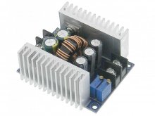
Well after all my bravado about building a load, I realized I bought one of these a few months ago with the intention of building an adjustable power supply out of it. It is rated at a max current of 15A and is constant current. I think it would be a lot easier to combine this with a big power resistor and use it for a constant current load. That way I can drain the entire series connected set of cells much more quickly.

Hard to imagine that little thing can handle 150W. I am definitely going to mount a fan on it.
36625-large.jpg

-Edit-

Scratch that, they claim 300W!!!

Might submerge it in dielectric oil instead.
 
Just ordered some power resistors.

0.1 ohm, 50W for discharging single cells.
1 ohm, 200W for discharging an 8S pack of cells.

Man that is a big honking resistor. I have a data mining cold plate and water cooling setup that would be perfect for that 200W resistor.


Better cancel the 0.1 ohm resistor. That DC-DC supply won't work off a single cell. I can still use it to test a full pack.
 
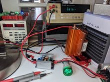
I decided to test the little Constant Current capable DC-DC buck converter I got from MPJA in the load mode.

I combined it with a 1 ohm, 200W power resistor and powered it from a 28V, 9A power supply.

Man that resistor got hot. The DC-DC converter had no problem running at 15A, but the resistor started smelling bad so I backed it off to 10A (100W). Even with a heat sink and a fan, that resistor is definitely not up to dissipating 200W.


PXL_20210129_210236488.jpg

I am going to get a 4 ohm, 500W resistor and try again. The DC-DC converter claims it can handle 300W and I am starting to believe it.

The combination of the 28V power supply and that little DC-DC converter has the makings of a decent battery pack charger. Didn't cost much either.

This could probably handle it. I think I am going to break out one of my bit-miner cold plates and switch to water cooling for this bad boy.

 
scratch that. I just bought 3 more of the 1 ohm resistors. 4 of those in series should make an adequate power sink. 800W rated. 400W real world.
 
The heatsink is very probably too small for that resistor.

Unlike the ceramic resistors those ones can barely handle 1/3 of their rated power without heatsinking.

It can also be a borderline design given it's from amazon ^^
 
The heatsink is very probably too small for that resistor.

Can't make it out well, but that heatsink on the bottom of the resistor appears to have fine pitch between fins.
Fan has large area. All air just goes around heatsink.
Heatsinks will have a rating in terms of degrees rise per watt at an air velocity. Perhaps ambient air speed, perhaps the speed of air forced between its fins.
If you had air being exhausted by a vacuum cleaner against the heatsink (or suction hose held against heatsink), that would probably provide enough cooling. At the very least, you wouldn't be able to hear any sizzling noises if it does overheat.

A much bigger heatsink would be preferred. One guy showed a small engine head being used that way.
 
Oh I know, it's probably a server CPU heatsink, so designed for pretty high velocity airflow. But even with proper airflow it's probably too small to have a low enough Rth.

Engine head is a bad idea, mainly because of the low surface area it offers.
 
Back
Top