diy solar

diy solar

EVE-280 cells should these be clamped tight or spaced for expansion?

320 W is a lot of heat. Just look at the amount of fans and heatsink necessary on a modern high end gaming graphics card, that has similar heat output. Yes there are more thermal mass, but in my application I also would go directly from discharge to high C charging. To put things into context i am building a diesel hybrid system with a large 30 kW diesel generator and a 10 kW inverter. The purpose of the batteries is to lower the required runtime for the diesel generator. Current will always run into or out from the batteries. There is no time for them to cool off.
320 watts is a lot of heat on one square inch of an IC, but not so much on about 170 pounds of battery.

Lithium titanate (LTO) technology might fit your use case better than LiFePO4. Crazy high charge and discharge rates combined with higher heat tolerance.
 
Yes the surface area of the batteries will help and heatsinks will therefore not be needed. The hot air does however need to go somewhere. Most put these in a box, but running this amount of heat in a closed box will cause the batteries to run hotter than necessary. Looking at the cycle life given in the datasheet of the LF280K and the LF280, temperature is just as important if not more important than compression. For people that care about the amount of cycles they get out of their batteries, cooling the batteries is important if running high C rates.

I do not expect to run higher C rates than 0.3-0.5 continuously, with short peaks up to 1-1.5 C. This should be well within the datasheet for the LF280K with proper cooling. If i planned on having 600-700 cycles a year, then it might make economical sense to move to LTO. However this system will only be used about 2 months a year with about 120-150 cycles within these two months. I am more than happy if i get 2000 cycles out of these batteries. That would be close to a lifetime of 15 years.
 
Fair enough. I am working on a battery build for my off-grid system that has old AGM batteries. My issue is heat as well, but not from internal generation. I need a low-power way to cool the battery compartment, so I'm holding off ordering cells until I figure out how I want to do it.

The "Easy Button" is LTO, but as you mentioned, the initial outlay is somewhat higher. LFP will require compression (no problem) and cooling. I'm looking at building a crazy thick foam box with a small refrigeration unit keeping it cool. The only real need for cooling is when the sun is out, so it can steal some panel power to run.
 
Hello,

I read all the posts off this thread and it was a lot :)
But I'm still a bit confused about how to reach the "good" compression value.

I'm planning to use fixed compression for 1p16s with 6 rods and bolts.
Does anyone has a simple way to translate 12psi or 300kgf to torque bench wrench value ?
 

Attachments

  • Pack 001.jpg
    Pack 001.jpg
    458.3 KB · Views: 27
Last edited:

Just be careful to get the units correct. It is a very small amount of torque compared to what you normally use to tighten bolts.
 

Just be careful to get the units correct. It is a very small amount of torque compared to what you normally use to tighten bolts.

I plan to use 6 rods (6mm) with M6 bolts.

If I understand correctly and if I don't make mistakes about unit conversions or translation:

I need to apply a total of 660lbs x 2 = 1320 lbs to keep it "compressed".
For 6 bolts: 1320/6 = 220 pounds at each bolt

With the bolt calculator i found:
  • 330 pounds (lbs) axial clamp force
  • bolt diameter = 0.23622 in (6mm)
  • torque should be set at: 10.40 in lbs (1.175 Nm) convert unit used (in lbs to Nm) for each bolt
It seems like not a lot of force, is my calcul wrong? :unsure:
Keep in mind that this is in inch lbs not feet lbs that torque wrenches normally use.
That is 0.86 ft lbs. Normally you torque a M6 bolt to about 7 ft lbs. So in this case you torque the bolt to about 1/10th of the normal correct torque on a M6.

I am more comfortable with metric so let me do a quick calculation to compare:

600 kgf (two cells worth of area)
1 kgf is 9.81 N (gravity acceleration)
5886 N / 6 = 981 N per rod.

Torque is converted to force with this formula

T = c D f
c is the coeffecient of friction
D is the bolt diameter
T is torque

T = 0.2 * 6 mm * 981 N = 1177.2 N mm = 1.177 N m

Yep, looks correct to me.

Thank you, for the very clear explanation!
I'm also more comfortable with metric system ;)

We reach the same result ?
 
Thank you, for the very clear explanation!
I'm also more comfortable with metric system ;)

We reach the same result ?
Note that torque is generally specified for dry threads. Lubricated threads need roughly 30 to 50 percent less torque to achieve the same preload on the bolt. I would make sure to not lubricate the threads for this application since overtorque may be much worse than undertorque.
 
Hello,

I read all the posts off this thread and it was a lot :)
But I'm still a bit confused about how to reach the "good" compression value.

I'm planning to use fixed compression for 1p16s with 6 rods and bolts.
Does anyone has a simple way to translate 12psi or 300kgf to torque bench wrench value ?

I am using Four 1/4 inch galvanized steel threaded rods on my 8S battery fixtures with the nuts were torqued to approximately 5 inch pounds using a torque wrench while my cells were about 70% charged. The wood end plates are 1x10" with thin plastic sheets between each cell. The fixture is more or less just retaining the cells with very little pressure applied. As has been mentioned in this thread the cells are snug.

I am currently not using a spring configuration.
 
Hello,

I read all the posts off this thread and it was a lot :)
But I'm still a bit confused about how to reach the "good" compression value.

I'm planning to use fixed compression for 1p16s with 6 rods and bolts.
Does anyone has a simple way to translate 12psi or 300kgf to torque bench wrench value ?
do you mind sharing your sketchup/3d file for this?
 
I plan to use 6 rods (6mm) with M6 bolts.

If I understand correctly and if I don't make mistakes about unit conversions or translation:

I need to apply a total of 660lbs x 2 = 1320 lbs to keep it "compressed".
For 6 bolts: 1320/6 = 220 pounds at each bolt

With the bolt calculator i found:
  • 330 pounds (lbs) axial clamp force
  • bolt diameter = 0.23622 in (6mm)
  • torque should be set at: 10.40 in lbs (1.175 Nm) convert unit used (in lbs to Nm) for each bolt
It seems like not a lot of force, is my calcul wrong? :unsure:
A better method, if your compression springs create roughly linear force through their working range, might be measure the springs instead. My own springs (4x per battery, 3 batteries) were purchased with a "maximum compression" value about 10% higher than the required force. Each Spring therefore, gets torqued down until they are 90% of the way to compressed height. (This varied according to the individual springs and the and the compression requirement, my 3 packs differ in size).

You will have a hard time finding Springs where the inner diameter is reasonably close to 6mm. On my comparable pack (4S, EVE 230Ah) I'm simply using 3/8 rod instead, purchased from a big box store. The nuts have an easier time, and the rods are stronger.

But I'm not familiar with your concept of calculating "double the load" for two sets of springs. I think you're making a mistake. If one end plate DIDN'T have springs, but simply consisted of steel plate (e.g. 1/4" steel plate) with the rods inserted through 'unsprung' holes, into a washer and nut on each one, that "plate" would still be feeling all 660 lbs from the other plate (tension via the rods, compression through the battery cells being equal).

The compression plate has the rod going through with about 2" of extra length, the spring mounted on the rod with a washer for the nut, and the tightening nut. When you tighten the nuts and compress your 6 rods TO ONLY 110 POUNDS EACH, 660 lbs of total tension occurs on the rods, and 660 lbs of compression occurs through the batteries - and through both plates.
- - -
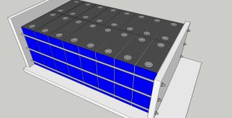
In fact, my first battery pack has double bolts. When cells expand, the centerline (between cells 2 and 3 of the 4S battery pack) remains motionless, while both end plates move out a slight bit. My later packs have only a single set of bolts. When cells expand, they push from the "fixed" un-sprung plate, moving towards the sprung plate. The total amount of motion remains the same, but the outer face of cell #4 gets moved twice as much (in comparison to the "equal movement" result of double sets). My battery cells are free to move along the bottom of the battery pack, with only the "left" side firmly anchored to the bottom. Fewer springs = less money and slightly less total length, same compression result.

If you build with "double" springs and start to compress one of your rods by tightening just ONE of its nuts, that spring will become compressed by only half the amount of movement on that nut. The opposing spring will also compress and take equal load. When you have the right compressed spring height (my distance method) or the correct torque (your method, probably less accurate due to imperfect beveling of the Thread faces, creating "tight" spots with uneven binding forces) your pack is fully compressed. The force on each tension rod is simply your total compression divided by the number of rods - no doubling.

With springs in pairs on the same rod, the nut on the spring which you are NOT turning will gain the same torque resistance as the nut which you ARE turning, through the rod and the compression of its own spring. If you go double the distance at one end, you don't need to move the second nut at all. They will be balanced.
 
My own springs (4x per battery, 3 batteries) were purchased with a "maximum compression" value about 10% higher than the required force. Each Spring therefore, gets torqued down until they are 90% of the way to compressed height. (This varied according to the individual springs and the and the compression requirement, my 3 packs differ in size).
Do you have any photos of your setup that you can share?
 
Do you have any photos of your setup that you can share?
I am still waiting for delivery of two steel end plates for the 230Ah battery pack, but here are photos of similar packs I built last year. The left one was 120Ah, the 105Ah was my first battery (constructed the same way). I built it with 4 springs on just one side, pulling the 1/4" steel plates together along 1/4" diameter "big box store" threaded rod segments. For my new and bigger battery pack, I'll be using 3/8 threaded rod with 4 bigger springs.

The second photo shows my first battery box (105Ah), I built an almost identical box for my second battery, and I will build nearly the same for my 3rd. (I didn't take a "final" photo of the 120Ah battery). In that first battery, there is some expansion room at the top, but not really enough at the bottom. The 4-sided wood box holds the BMS above the bus bars (using a small separator to prevent contact), and includes a fuse inside. The wood top is screwed down into the side plates, and it's removable for fuse replacement or other unexpected battery maintenance.

The battery "left plate" is glued to the wood vertical "side" on the left (with the springs), but the upper right side side has a small gap between the wood "side" and the metal plate. That allows for a small amount of swelling and shrinkage, according to the State of Charge, between the pack's right-hand plate and the right side. If I ever bother to make this old one "perfect", then I should stretch the distance between the lower right side and the metal plate to provide similar room. That "final" battery assembly also includes a 12v heating pad, not relevant to this discussion.

I didn't install the fuse (taped on top of the 105Ah) until final installation into the RV travel trailer. In both batteries I used springs which were rated only about 15% above their maximum compression rating (at fully compressed height), and you see that the springs are correspondingly compressed - being just slightly taller than their fully compressed height. While tightening the spring-loaded bolts, I measured the height of each spring (carefully, within 1mm) to create proper total compression on each pack.
 

Attachments

  • 120ah-battery-ready-for-taping-and-case.jpg
    120ah-battery-ready-for-taping-and-case.jpg
    265.8 KB · Views: 68
  • HomeBuilt-105Ah-number-one-with-heating-pad-and-partial-wood-case.jpg
    HomeBuilt-105Ah-number-one-with-heating-pad-and-partial-wood-case.jpg
    329.6 KB · Views: 67
Last edited:
When you compress the cells together, you’re increasing the life cycle of the batteries. If your batteries are rated 4000 cycles, that’s under a compress state. Compression is where you prevent the bulge or swelling of the cells by using various methods.. taping, strapping or enclosing the batteries in a fit case. Without compression, you can loose half the life cycle of the batteries
 
It is the sides of the aluminum can that swells under internal gas pressure, not the actual internal cell pouches.

Actual cell pouch wraps for aluminum cased LFP cells do not swell like self-contained sealed pouch cells. The aluminum cased internal plastic wrapped pouches are open at top of wrap and any electrolyte decomposition gas just diffuses from top of pouch wrap to internal aluminum case. Aluminum casing is sealed and provides the environmental seal to outside.

It is important the terminal plastic grommets not be side torqued or rotated as they need to maintain their seal to aluminum case top.
 
Off Grid Garage's video from couple weeks ago is pretty relevant to this discussion :)
I have seen the video from Andy.

He is forgetting one main thing, that the cells are supposed to have a snug fit.
To prevent bulging, the walls of the cells simply are too weak to prevent this on their own in the long run.

2000-4000 cycles..
With charging during daytime and using 50-70% at night...
They can last ages.
Maximum life expectancy under most optimal conditions is 20 years.
They aren't Edison batteries!!

How stupid would you feel to ignore the guidelines given by the producers, who do that "extra mile" themselves when constructing their own packs?

You really believe Andy has more knowledge then the engineers over at BYD or EVE??

The whole spring "hoax" is over the top. "Too much of a good thing".
It won't hurt, also won't increase compared to a snug fit.

Can anyone produce a picture or video of 280ah cells that aren't snug / clamped after 2-3 years of continuous use?
And the same type with a snug fit?

Without it ..
We need to choose:
Follow Andy's logic, or the factory engineering team.

Up to you ☺️
 
It is the sides of the aluminum can that swells under internal gas pressure, not the actual internal cell pouches.
No. No gas is generated by LFP cells during normal charge-discharge cycles.

The cathode material (Lithium Iron Phosphate) actually changes size with state of charge as the Lithium ions move (in for charge; out for discharge, which leaves Iron Phosphate for a fully discharged cell). I can't find the paper that stated this best, but I did find this interesting one tonight. I hope your acronym bill is all paid up. They use a lot of them!

Prediction of compression force evolution over degradation for a lithium-ion battery
 
Do not lay prismatic cells on their sides!
I just did three 17 cells installs, all on there side. I haven't seen anywhere in the specs or data supplied with the Eve 280ah cells, not to.
Is there anyone here that has problems and has their cells on the side ?
 
No. No gas is generated by LFP cells during normal charge-discharge cycles.

The cathode material (Lithium Iron Phosphate) actually changes size with state of charge as the Lithium ions move (in for charge; out for discharge, which leaves Iron Phosphate for a fully discharged cell). I can't find the paper that stated this best, but I did find this interesting one tonight. I hope your acronym bill is all paid up. They use a lot of them!

Prediction of compression force evolution over degradation for a lithium-ion battery
The cell bloating everyone sees is due to electrolyte decomposition, usually from overcharging, although it can also be caused by other things like charging at cold temperature. For the aluminum cased cells this is just an expansion of metal case from the increased internal gas pressure and the actual cell wrap laminates do not expand from the electrolyte decomposition gases. The gases from any electrolyte decomposition escapes the open end of laminate wrap increasing pressure within the metal container but not expanding the actual cell lamination layers wrap.

Compression has absolutely no benefit to reducing degradation of cell due to electrolyte decomposition. As long as the overpressure vent port is not breached, the real damage due to electrolyte decomposition is not the gas, it is the other decomposition tar products that clog up the electrode pores that increases cell impedance. The created gas and cell mechanical compression can only increase metal container pressure by restricting the internal volume of cell casing, so it is more likely to breach the overpressure vent port. If this happens the cell is open to atmosphere and electrolyte solvent will eventually evaporate through the breached vent port.

Total cell expansion due to graphite anode expansion at full state of charge is almost imperceptible, in the range of 1 to 2 mm for a 280 AH 72 mm wide cell. The EVA spec actually claims only about 0.5 mm in the 72 mm width between 30% and 100% state of charge but I don't believe that number. There might be enough tolerance between the width of internal cell wrap dimension and aluminum case dimension to absorb much of the graphite expansion.

Graphite anode volume expansion at full charge is about 9-11%. Graphite is about 20% to 25% of cell volume so net cell expansion is about 10% of 23%, or 2.3 %. Although 1-2 mm per cell is not much, when you stack 8 or 16 cells side by side it adds up and can significantly increase mechanical compression pressure when there is a hard fixed, non-compliant compression container.

The expansion of graphite anode at full charge can cause fracturing and electrical islanding isolation of chips of graphite anode making less graphite participating in cell primary lithium-ion intercalation function and increasing cell impedance. Compression is unlikely to have any benefit in preventing graphite fracture and may even cause more fracturing of the graphite if compression pressures get too great.

Primary benefit of compression is to reduce graphite and LFP electrode material delamination from the copper and aluminum foil, respectively, which will increase conductive series resistance of cell. This delamination is accelerated when cell is subjected to high charge and discharge currents resulting in higher internal temperature induced stress on the bonding of electrode material to metal foil current collectors. If you don't subject cells to high charge and discharge current, there is insignificant benefit to compressing a cell and risk of actually damaging cell with too much compression pressure.
 
Last edited:
Off Grid Garage's video from couple weeks ago is pretty relevant to this discussion :)
His argument is akin to, "you can't live a long life because smoking or hang gliding or the beer truck will kill you first." What if you don't smoke or hang glide, and you put a GPS tracker on the beer truck so you know when it is in the neighborhood? I see cell compression the same as eating well and getting regular exercise.
 
The cell bloating everyone sees is due to electrolyte decomposition, usually from overcharging, although it can also be caused by other things like charging at cold temperature. For the aluminum cased cells this is just an expansion of metal case from the increased internal gas pressure and the actual cell wrap laminates do not expand from the electrolyte decomposition gases. The gases from any electrolyte decomposition escapes the open end of laminate wrap increasing pressure within the metal container but not expanding the actual cell lamination layers wrap.

Compression has absolutely no benefit to reducing degradation of cell due to electrolyte decomposition. As long as the overpressure vent port is not breached, the real damage due to electrolyte decomposition is not the gas, it is the other decomposition tar products that clog up the electrode pores that increases cell impedance. The created gas and cell mechanical compression can only increase metal container pressure by restricting the internal volume of cell casing, so it is more likely to breach the overpressure vent port. If this happens the cell is open to atmosphere and electrolyte solvent will eventually evaporate through the breached vent port.

Total cell expansion due to graphite anode expansion at full state of charge is almost imperceptible, in the range of 1 to 2 mm for a 280 AH 72 mm wide cell.

Graphite anode volume expansion at full charge is about 9-11%. Graphite is about 20% to 25% of cell volume so net cell expansion is about 10% of 23%, or 2.3 %. Although 1-2 mm per cell is not much, when you stack 8 or 16 cells side by side it adds up and can significantly increase mechanical compression pressure when there is a hard fixed, non-compliant compression container.

The expansion of graphite anode at full charge can cause fracturing and electrical islanding isolation of chips of graphite anode making less graphite participating in cell primary lithium-ion intercalation function and increasing cell impedance. Compression is unlikely to have any benefit in preventing graphite fracture and may even cause more fracturing of the graphite if compression pressures get too great.

Primary benefit of compression is to reduce graphite and LFP electrode material delamination from the copper and aluminum foil, respectively, which will increase conductive series resistance of cell. This delamination is accelerated when cell is subjected to high charge and discharge currents resulting in higher internal temperature induced stress on the bonding of electrode material to metal foil current collectors. If you don't subject cells to high charge and discharge current, there is insignificant benefit to compressing a cell and risk of actually damaging cell with too much compression pressure.
Several folks here have shown cell swelling with one top balance charge.

The LFP chemical equation, as far as I can tell:

The cathode reaction is:
LiFePO4 ⟶ FePO4 + Li(+) + e(−)

The anode is:
Li(+) + C6 + e(−) ⟶ LiC6

I can't find any papers that discuss any significant gas generation during charge or discharge of an LFP cell. Please cite a source so I can learn.
 
This is just anectdotal information in response to an earlier question about cells in horizontal configuration. In that configuration I had one cell leak electrolyte. I am still using it in a larger pack, all of which are verticle and clamped.
 

diy solar

diy solar
Back
Top