diy solar

diy solar

feedback: this forum has convinced me not to build a solar system.

Ok I'll look deeper into it. Is there a particular model number you're referring to? Any idea if it is capable of passing a generator through, and/or charging the batteries using grid power?

Search for threads started by @42OhmsPA


As for short ROI- yes, but I'm willing to give up $1400 extra for a battery pack that is purpose built with everything nicely tucked inside.

You could buy a specially made box for another $500, or cover anything exposed with plexiglass and tape.

$1400-1600 buys a lot of pv. Or a mini split for your garage so you can put the parts inside. Etc etc.

But I understand if you would rather just buy a battery
 
Not sure that LiFePO4 batteries generate much heat, charging or discharging. FET BMS to have I^2R power.

The LFP batteries generate very little heat when charging or discharging at high rates and pretty much none at low rates.


Ok I'll look deeper into it. Is there a particular model number you're referring to? Any idea if it is capable of passing a generator through, and/or charging the batteries using grid power?

As for short ROI- yes, but I'm willing to give up $1400 extra for a battery pack that is purpose built with everything nicely tucked inside. I'm a very paranoid person, especially about high-current wiring (due to a previous career of mine). Every exposed wire/terminal I see is another nightmare I have about arc, visitors who get injured due to ignorance, father-in-laws accidentally putting a shovel across battery terminals, etc. The $1400 buys me both peace of mind, and many hours back in not having to build it myself, and then build a shell for it myself, and then build a bracket for the shell myself, and on and on.


I plan to DIY batteries, but that suits my temperment - and you are making the right choice for you from what I read. It takes minimum 3 months obsessing over battery building to learn all the ins and out of doing it perfectly. Anything less than perfection is a risk. Oh yes, when building a DIY battery you must chant "be the borg, I am a borg, resistance is futile" the whole time. Channel your inner borg.

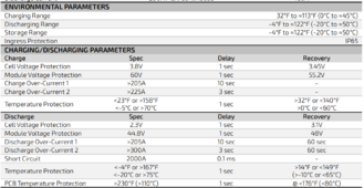
Enclosing it isn't required - it has an inbuilt heater to keep the battery cells at 32f - It does consume power so it might make sense to keep it from getting sooo cold, so that 224w (5Khrs per day) stays in the battery or available for use. Or put out another 1200w of panels to offset that in a day. Like any heater I am sure it cycles off and on so it isn't actually running all the time, just depends on temp.


1720801311990.png


1720801771505.png
 
Last edited:
Winter starts Nov 1 here, so I need to get the thing together pretty quick. I love DIY too, but the scale of this project demands some $ exchanged for expediency. Also if I tell my wife I DIY'd the batteries she is going to get upset.
Try this instead, not hard to do.

Getting cells top balanced with an active balancer is easy too.
 
If you have any shading, i tis better to have the shade in one MPPT and not the other as much as possible.

Trying to keep all panels on the MPPT as close to each other as possible keeps them all performing similarly.
Mike could I ask you to expand on this? I don't understand why it is better to have shade in one and not the other.

What does it mean for the panels to perform similarly? Do they lose efficiency (?/amps?/volts?) if some panels are producing less power than others?

Does it affect the MPPT circuitry to have some panels shade and some sun?

Thanks
Panels in series are like cells of battery (Only as strong as the weakest link) diodes in some panels can combat this to an extent. You can also use Optimizers or micro members to combat this at further expense.
 
If two PV strings in parallel, e.g. 4s2p, better to have shade on one panel per string so like 3s2p, rather than on 2 panels of one string so like 2s || 4s.

But some MPPT get confused with any shade and don't find maximum power point.
In that case better to wipe out one string and leave the other unshaded.

Want MPPT to find global maxima, not stop on local.


I have a 2S6P arrangement where 70% of my panels are shaded at any time. My controller gets lost all the time. This was such a problem that I have a control that disconnects the array from the charge controller should it drop below a certain voltage. It always comes back to the right voltage after that. Controllers only probe a nearby region and they can seek and hold on to a lower power peak. For simplicity 2S2P, one panel is shaded and goes into bypass. The controller will see a current peak looking like 1S2P and latch onto that. Even a shaded panel produces power. I can actually run with ambient light in rain conditions. A shaded string will still produce some power when in parallel. Shaded panels do not produce power in bypass and actually reduce power from the string. A few rare controllers have a settable lower voltage they will not go below.
 
Want MPPT to find global maxima, not stop on local.
Thanks. Let's see if I understand correctly:

So the goal here, if I understand it correctly, is to prevent the Panels from climbing too high in voltage and thus having the current fall to 0?

The method the MPPT uses to do that is to adjust impedance until it finds a maximum?

Some MPPTs halt adjustment once a maximum is found so they will find local maxima instead of global?

In my system I'm intending to put 10 panels in series onto MPPT1. I'm intending to put a different 10 panels in series into MPPT2. The current design has 50.1% of MPPT1's panels in shade, and 50.2% of MPPT2's panels in shade.

I do not have any panels in parallel in my design (although I might do that in the future). I haven't done the math yet, but I can see how trying to set impedance for two things in parallel could be difficult if the things in parallel are not close together in their impedance.

I think what was proposed to me earlier in this forum is that I should do my best to group all shaded panels into MPPT1, and all full-sun panels into MPPT2- is that correct? Or is it the opposite?


Something I don't understand: If the MPPT is adjusting impedance, wouldn't it simply adjust to maximize the highest output voltages in your string (sunny)? In the cell IV curve, current is flat at lower voltages so it seems like an MPPT's local maxima should also be the global maxima for series-strings that include shaded (lower voltage) panels?

Essentially for a series-string, the MPPT is going to see a ONE voltage input, and a current that goes with that after impedance is set. As the impedance is adjusted, current will vary. Current will exponentially fall off (according to series IV chart above) if impedance is too low. If impedance is too high, current will slowly/linearly fall off according to series IV chart. Seems relatively easy to find a global maximum under those conditions, no?
 
Thanks. Let's see if I understand correctly:

So the goal here, if I understand it correctly, is to prevent the Panels from climbing too high in voltage and thus having the current fall to 0?

That is the basic functionality, although target isn't current > 0, target is to maximizecurrent x voltage = power.


That curve shows current decreases (on an inverse exponential curve), reaching 0A at Voc.

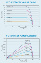
The curve you need is W = V x I vs. V
1721658297617.png


Note that maximum power occurs at around 85% of maximum voltage.
MPPT starts at Voc, pulls current lower while calculating wattage, finds the peak, dithers back and forth to stay at the peak.

The method the MPPT uses to do that is to adjust impedance until it finds a maximum?

Typically a buck converter, increases current by varying switching duty ratio to find that maximum.

Some MPPTs halt adjustment once a maximum is found so they will find local maxima instead of global?

Exactly. Draw more current until power starts to decrease again, dither back and forth to stay at the (local) maxima.

If at lower voltage there is a dip to lower power, then climbs again to an even higher power, it never finds that.

In my system I'm intending to put 10 panels in series onto MPPT1. I'm intending to put a different 10 panels in series into MPPT2. The current design has 50.1% of MPPT1's panels in shade, and 50.2% of MPPT2's panels in shade.

That works, 10 panels MPPT 1 sometimes full sun, sometimes 5 panels shaded.
10 panels MPPT 2 similar situation.
So long as 5 x Vmp is within MPPT operating voltage, should work.

But, make sure no panels get shaded while others in series get full sun. That will push full current through bypass diodes, can cause diodes to fail and panel to melt or crack. Try to have shadows only fall on panels with light is at about 45 degree angle or beyond.

I do not have any panels in parallel in my design (although I might do that in the future). I haven't done the math yet, but I can see how trying to set impedance for two things in parallel could be difficult if the things in parallel are not close together in their impedance.

Two strings in parallel is OK if all panels are unshaded, even though sun is off-angle for panels of one string.
Note in curves that greatly reduced sun only reduces Voc and Vmp a percentage.

Ok for partial shade too, probably best if no more than 15% difference in shading so Vmp remains similar.
This is where you can try to arrange for shade to start impacting panels on both strings at same time.

Also note arrangement of cells and bypass diodes in panels. Shadow on end (short side) of panel would take out all 2 or 3 sub strings. Shadow on long side would only take out 1/3 or 1/2 of its production. If multiple rows of panels can shade each other, "landscape" orientation should reduce loss due to partial shading.


I think what was proposed to me earlier in this forum is that I should do my best to group all shaded panels into MPPT1, and all full-sun panels into MPPT2- is that correct? Or is it the opposite?

Having one string unshaded means even a dumb MPPT should work OK. In this case better to have all shaded panels in one MPPT.

If 5s panels causes voltage to drop below where MPPT works, then with all shade encroaching on one string, when 25% of your 20 panels are shaded, one entire string stops producing and 10 panels remain.
If shade encroaches on on both strings equally, then when 25% are shaded, that leaves 14 or 16 panels producing. Only when 50% of panels are shaded does production drop to 10 panels.

Sun good, shade bad.


Something I don't understand: If the MPPT is adjusting impedance, wouldn't it simply adjust to maximize the highest output voltages in your string (sunny)? In the cell IV curve, current is flat at lower voltages so it seems like an MPPT's local maxima should also be the global maxima for series-strings that include shaded (lower voltage) panels?

See above. Maximum W = V x I, not maximum V (which occurs at I = 0A, W = 0)

Essentially for a series-string, the MPPT is going to see a ONE voltage input, and a current that goes with that after impedance is set. As the impedance is adjusted, current will vary. Current will exponentially fall off (according to series IV chart above) if impedance is too low. If impedance is too high, current will slowly/linearly fall off according to series IV chart. Seems relatively easy to find a global maximum under those conditions, no?

Yes, current falls of as voltage increases.

If MPPT sweeps voltage from Voc all the way down to zero, it will pass through local and global maxima. Then it can return to global maxima and sit there for a while.

It will dither and stay on top of the maxima it is at. But if lighting changes that may become a local, not global maxima. And there it sits.

So, after a while, a good MPPT will sweep again to see if there is a new global maxima.


Wouldn't bypass diodes eliminate the problem of having some shaded panels in a string?


Bypass diodes make it possible for a 10s string to put out the power of 9s string when one panel is shaded.
Without the diode, current would drop to zero.

With some light falling on the panel, it may produce 1A instead of 10A, and MPPT might not pull voltage low enough to benefit. Requires decent MPPT algorithm with global sweep.

I think (but haven't yet used) half-cut panels which are internally wired 2p3s. If shade falls on a single cell, current drops from 10A to 5A. Good solid power being produced, but instead of 1/2 power it could produce 2/3 power at lower voltage. A 10s string would drop to half current (and somewhat higher voltage). This would reduce power to 1/2 (or a bit more) when it could have been 29/30th. I don't know for sure, but think a dump MPPT would be easily confused.
 
Thanks very much! Would be nice to have an explanation like this pinned somewhere.

I see what you mean now, about Watts instead of Ohms. Essentially current is limited not by the internal resistance of the panel, but by how much sun is being converted into power, and since the voltage doesn't change much (after the electrons jump the gap), current goes as power production goes.

But, make sure no panels get shaded while others in series get full sun. That will push full current through bypass diodes, can cause diodes to fail and panel to melt or crack.
Is this a significant concern? Of my two panel strings, one is going to have dramatic changes in shading. Should I consider beefing up the bypass diodes, or wait until after they fail to do this?

Also note arrangement of cells and bypass diodes in panels. Shadow on end (short side) of panel would take out all 2 or 3 sub strings. Shadow on long side would only take out 1/3 or 1/2 of its production. If multiple rows of panels can shade each other, "landscape" orientation should reduce loss due to partial shading.
Great tip; I had not thought of that.

Having one string unshaded means even a dumb MPPT should work OK. In this case better to have all shaded panels in one MPPT.
So, after a while, a good MPPT will sweep again to see if there is a new global maxima.
I'm planning to use the EG4 6000XP; any idea whether where the 6000XP's MPPT falls on this dumbness spectrum, and whether it will make frequent sweeps?


Bypass diodes make it possible for a 10s string to put out the power of 9s string when one panel is shaded.
Without the diode, current would drop to zero.

With some light falling on the panel, it may produce 1A instead of 10A, and MPPT might not pull voltage low enough to benefit. Requires decent MPPT algorithm with global sweep.
I'm intellectually struggling to grasp this still. The shaded panel will be bypassed by diodes when condition (?voltage differential?) is met. The MPPT has some effect on that condition by sweeping through (?power input?). Maybe I need to look up Buck Converter and MPPT circuitry and learn more about it.

edit: based on the message you sent on Friday with the chart, I believe the MPPT is somehow adjusting voltage across the string and looking for power maxima. adjusting the voltage could push under/over the bypass diode's voltage, allowing/blocking current from the shaded section.


I think (but haven't yet used) half-cut panels which are internally wired 2p3s. If shade falls on a single cell, current drops from 10A to 5A. Good solid power being produced, but instead of 1/2 power it could produce 2/3 power at lower voltage. A 10s string would drop to half current (and somewhat higher voltage). This would reduce power to 1/2 (or a bit more) when it could have been 29/30th. I don't know for sure, but think a dump MPPT would be easily confused.
Could you please remind me what the notation 2p3s means? I've ordered these panels from Hyperion where the spec says (6x18).
The rest of the math here makes sense to me -- if each module has 3 strings in series, then you hope to have a setup where the shaded string is bypassed thru the bypass diode, and the other 29 strings march onward.

Found a technical explanation of bypass diodes here.
 
Last edited:
This gives me a solar instrumentation idea. Build in taps on each panel/diode and pipe to a mux. Have a computer (arduino/pi/etc) sweep through the mux measuring volts/amps at each point. Display realtime entire system electrical health for user in an app or html.
 
3s2p would be 3 panels in series, another 3 panels in series, then connect those 2 strings in parallel.

2p3s would be 2 panels in parallel, another 2 panels in parallel, another 2 panels in parallel, then connect those 3 sets in series.

Panels would always be connected nSmP. Batteries sometimes done either way.
But inside a half-cut panel they're usually wired 2p3s.


Some brands of panels are OK with full Imp being pushed through diode, but some the documents say specifically not to do that. We've seen pictures of melted plastic and cracked glass.

Locate and orient your string of panels so no obstructions are at 90 degrees orthogonal to them. Maybe at 45 degree angle.
 
This gives me a solar instrumentation idea. Build in taps on each panel/diode and pipe to a mux. Have a computer (arduino/pi/etc) sweep through the mux measuring volts/amps at each point. Display realtime entire system electrical health for user in an app or html.

That works at the panel level. Tapping the diodes will require breaking into the panel junction boxes.

Note that the voltages will be high, maybe 400-500 volts, when measured relative to system ground.

Also note that HF inverters often oscillate the PV voltage rails so they track the AC output (which removes a conversion stage in the inverter design). This will make measuring the voltages and currents that much harder.

Mike C.
 

diy solar

diy solar
Back
Top