diy solar

diy solar

Finally found a LiFePO4 BMS with Low-temp Charging Protection

Chart was all squished together. Sorry everyone

Here is how to interpret a line of data

1700 117 Amps 40.8C 27.2C 39C 37C

5 pm, Amp discharge rate of 117A, First temp is BMS 40.8 Celcius, 2nd temp is battery pack 27.2C, next temp is three wire negative to battery pack from BMS at 39C, and last is the short two wire connector you can see on the pack instead of a longer bus bar between cell group 2 and 3 and is 37C
 
Take home points.

I ran the BMS at above spec (Spec is 120 amps) to 147 amps discharge load for 10 min and it handled it with modest temperatures on BMS, Wires etc.
All alarm parameters work as advertised including all temperature cutoff alarms
Handled a 113-147 AMP continuous load for 4 hours and 21 minutes flawlessly. Highest BMS Temp was 45.5C, Battery pack 33.1C, and three wires 51C

Not sure of longevity of the product of course

Rate at 10/10 as best BMS that does exactly what it is advertised to do and at a killer price. I will run my whole sailboat using these with 1-2 spares on board.

Thanks to Will for spotting these, ordering, and doing first test on his YT channel...
 
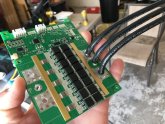
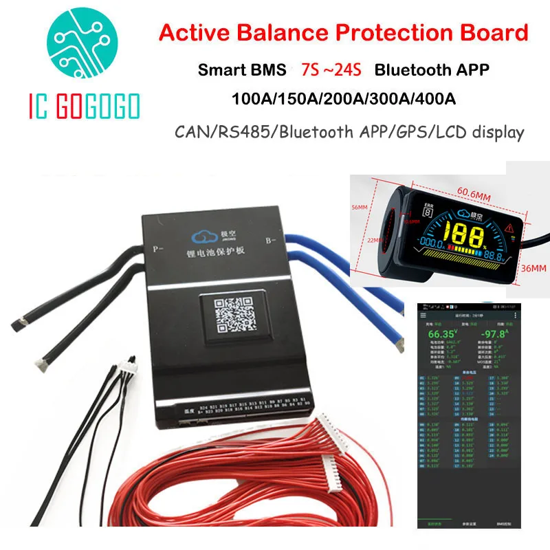
Hello Everyone. Big update on my LLT Power 4S LiFEPO4 120 Amp BMS with Bluetooth (SAME as Will's but 120 Amp version)

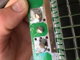
I switched the input and output wires to silicone 8 gauge x 3 per side which is equivalent to 3 gauge effective size.


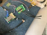
Here are some pics of the app and of my dinning room table workshop. 4 more cells to come from Amy and I will be able to make up the 1120 AH pack.


View attachment 8672
IIRC, you said you crimped the 3 8AWG wires into 1 battery lug. Do you remember what size lug you used for this?
The 8AWG wires are a pretty big mass, what temp did you set your station at to solder them in place and not get a cold joint?
I haven't soldered anything in a long time, but I'm thing of getting a solder station. Maybe a KSGER T12 digital.

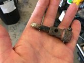
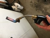
Used BNTECHGO Silicone soft wire 8 gauge. Bought off their website two 50 Ft spools, Lugs were 4AWG. Yes three wire into lug and hydraulic crimper. You can see all tools used in pics. Used torch and solder heat gun to set solder . Solder is 1.5 mm, 2% flux. Ground down solder of original wires with dremmal tool to pull them out
 
Hello Everyone. Big update on my LLT Power 4S LiFEPO4 120 Amp BMS with Bluetooth (SAME as Will's but 120 Amp version)

I switched the input and output wires to silicone 8 gauge x 3 per side which is equivalent to 3 gauge effective size.

(https://www.aliexpress.com/item/4000425316662.html?spm=a2g0s.9042311.0.0.38e94c4dDlIoAU)

TEST TODAY

Set new high and low cutoffs to test for the final setup to stay off the most vertical part of the discharge/charge curve (the knees) where very little amp hours are gained at either end yet voltages are pushed low/high.

Set:

Cutoff high: 3.50V per cell
Cutoff low: 2.90V per cell

Testing the following on my new EVE 280 AH cells in a 2P4S configuration (560 AH bank) from Amy at Shenzhen Xuba Electronic Trading Co. The other bank being made is a 4P4S x 280AH. so a 1120 AH pack. All for our offshore sailboat.

1. Usable capacity test for these new high/low cutoffs at .20C (Approx 112-120 Amps): Klien 505AH, 483 AH with DROK Meter: Will use these parameters.
2. Over current test of BMS, with BMS protection in app set to 160 amps. Ran at 147 amps discharge for 10 minutes. BMS board temp was 45C (normally at 112 amps 39.5C) and 3 wires were 35C. BMS handled load with no issues. Did not want to push further. Worked Perfectly
3. Tested high current discharge cutoff, Worked Perfectly
4.Tested high and low voltage cell cutoffs, Worked Perfectly
5. Tested High Temp Cutoff, works. Put heat gun load pointed at temp sensor, 65C set and shut down system. Worked Perfectly
6. Tested low temp cutoff discharging, works (salt ice solution, -10C set in app). Worked Perfectly
7. Tested low temp cutoff charging, 0C, Worked Perfectly

Measured amps with Klien CL380 as DROK Digital DC Multimeter Hall sensor was off 5-10 amps under for most of test

Test started at 1528 BMS Temp Battery Pack Negative 3 wire 2 wire on battery

1528 147 Amps
1538 147 Amps 44.9C 24 35C -
1539 113.6 Amps
1602 113.6 Amps 39.4C 25C 36C 36C
1620 115 Amps 39.7C 26C 37C 35C
1700 117 Amps 40.8C 27.2C 39C 37C
1730 117.5Amps 41.7C 28C 40C 37C
1800 116.2Amps 41.4C 29.7C 45C 39C
1830 120.2Amps 42.8C 30.9C 45C 41C
1900 118Amps 44.3C 31.8C 51C 43C
1930 121Amps 45.5C 33.1C 51C 45C
1951 121Amps (TEST ENDED LOW VOLTAGE CUTOFF CELL 3, 2.90V)


Therefore with above cutoffs 90% of battery capacity available still with a bit more of a safety cushion


Here are some pics of the app and of my dinning room table workshop. 4 more cells to come from Amy and I will be able to make up the 1120 AH pack.
Thanks for the detailed review and recommendations. It is a great help!

I purchased a 100 amp model for my sailboat from Battery Hookup but think ill use that as my spare and get one of these.

Your pack looks great. Did you make the busbars yourself?

Thanks
 
Thanks for the detailed review and recommendations. It is a great help!

I purchased a 100 amp model for my sailboat from Battery Hookup but think ill use that as my spare and get one of these.

Your pack looks great. Did you make the busbars yourself?

Thanks
I wonder if the position of the 3rd wire is connected on the PCB? I wonder if the difference between the 100A and 120A is just the 2 wires and maybe he firmware?
 
Thanks for the detailed review and recommendations. It is a great help!

I purchased a 100 amp model for my sailboat from Battery Hookup but think ill use that as my spare and get one of these.

Your pack looks great. Did you make the busbars yourself?

Thanks
No those came with batteries, for loads on a sailboat should not be an issue. Put red shrink insulation on.
 
I wonder if the position of the 3rd wire is connected on the PCB? I wonder if the difference between the 100A and 120A is just the 2 wires and maybe he firmware?
I think there is no difference. All three wires are connected of course. I think all the units are the same, only difference is numbers of wires and gauges when they sell. Just a suspicion... I bet it may handle a little more than 120 continuous with right wire gauges but my loads are never more than 30-50 amps most of time so no issue.

No those came with batteries, for loads on a sailboat should not be an issue. Put red shrink insulation on.
 
I think there is no difference. All three wires are connected of course. I think all the units are the same, only difference is numbers of wires and gauges when they sell. Just a suspicion... I bet it may handle a little more than 120 continuous with right wire gauges but my loads are never more than 30-50 amps most of time so no issue.
I phrased that wrong. I wonder if the hole on the PCB is connected and I don't see them making different PBCs. So, if you change the 100A version to three 8AWG wires like you did, how much could it handle. I have both 100A and 120A versions, but I'm not going to pull the heat-sinks off to see if there's a difference.
 
I am looking to purchase one of these DYKB BMS my 4S 150AH pack (currently using electrodacus SBMS40), I charge via my alternator (30A Renogy DC to DC) and my largest load will be a 600W DC water heater (https://www.aliexpress.com/item/4000045321254.html). So my max usage will be 30A going in and up to 60A going out simultaneously.

My questions are:
Should I go for the 100A or 120A?
Once I hit max charge from my alternator, I want the BMS to automatically shut off charging when any of the cells hit 3.5V, can this BMS safely disconnect a 30A charge load?
It will safely disconnect a 120A load or higher. I have a 120 amp alternator with smart regulator, solar panels and a 65 amp wind gen...Always overbuild so a 120 amp version for sure. I will have a 1120 AH bank and a 560 AH bank on my boat will all types of inputs and outputs along with a alternator protection device and a Lead acid battery always connected so the alternator is not open circuited at any time when the high voltage cutoff disconnects a battery. Essential so you do not blow the alternator.
 
Helpful, thank you
The 100A has 2x 10awg leads?
120A has 3x 10awg leads?

Electrodacus is very concerned with shutting off high charging loads and insists on using chargers that can be turned off remotely (as opposed to the electrodacus shutting off the charge) Just want to triple check that my proposed setup is safe
 
I am looking to purchase one of these DYKB BMS my 4S 150AH pack (currently using electrodacus SBMS40), I charge via my alternator (30A Renogy DC to DC) and my largest load will be a 600W DC water heater (https://www.aliexpress.com/item/4000045321254.html). So my max usage will be 30A going in and up to 60A going out simultaneously.

My questions are:
Should I go for the 100A or 120A?
Once I hit max charge from my alternator, I want the BMS to automatically shut off charging when any of the cells hit 3.5V, can this BMS safely disconnect a 30A charge load?
What about your current setup is not working for you?
 
Helpful, thank you
The 100A has 2x 10awg leads?
120A has 3x 10awg leads?

Electrodacus is very concerned with shutting off high charging loads and insists on using chargers that can be turned off remotely (as opposed to the electrodacus shutting off the charge) Just want to triple check that my proposed setup is safe
I never leave chargers connected on my boat. All lithium batteries are disconnected other than small lead acid on shore power charger For bilge pumps etc. It’s really not so complicated
 
I phrased that wrong. I wonder if the hole on the PCB is connected and I don't see them making different PBCs. So, if you change the 100A version to three 8AWG wires like you did, how much could it handle. I have both 100A and 120A versions, but I'm not going to pull the heat-sinks off to see if there's a difference.

The PCB might be the same but they can populate only 8 mosfets on a total of 10 for example, or use the same number but different mosfets.
 
Back
Top