diy solar

diy solar

Finally found a LiFePO4 BMS with Low-temp Charging Protection

I have the same question. Why two of each. Do these wires connect to the pos and neg terminals on the battery?

No , both the b- goes to the battery - and both of the c - goes to the common ground. The bms will interrupt the ground connection to essentially cut off the power supply in the event of a problem. Apparently they use the 2 smaller wires per side to carry the 100amp load instead of 1 larger one (like the Daly), which makes the install a bit messy but it is working just fine for me.
 
No , both the b- goes to the battery - and both of the c - goes to the common ground. The bms will interrupt the ground connection to essentially cut off the power supply in the event of a problem. Apparently they use the 2 smaller wires per side to carry the 100amp load instead of 1 larger one (like the Daly), which makes the install a bit messy but it is working just fine for me.
Thanks for this. Will I be ok twisting the wires together and then splicing to some six gage welding wire using a connector like this ...
 

Attachments

  • 293D40C1-D757-4DB6-9955-AAE1BF132DE4.png
    293D40C1-D757-4DB6-9955-AAE1BF132DE4.png
    329.5 KB · Views: 35
Putting together a 100aH, 4S bank with this BMS. I can't seem to find the configuration video, so I have a couple of questions:

I see two spots in the parameter settings to set the low temp discharge cut off. One says -10, the other 0. I'm guessing change the -10 to 2 and leave the other alone, but just checking.

Once programmed they way you like it, can the bluetooth module be unplugged? Meaning does the BMS need it plugged in to operate?

Thanks!
 
I'm not sure exactly which parameters you're looking at, but IIRC LFP can be discharged at -10C, but charging should be cut off at 0C.
That may be what you're seeing. Or I may not know what I'm talking about, too.
I guess you could unplug the BT, but why? You won't be able to monitor the system.
 
Stag, yes, I messed up on the charge/discharge. But there are two entries for both and I want to edit the right one.

I'd rather lose the bluetooth dongle because it is just another power thief most of the time. As well, the app is slow to change screens and is not as sensitive/accurate as the battery monitor I have to use with the battery bank.
How did you deal with the black and blue wires? I plan to twist them together and use a wire lug splice to connect with some 6 gage welding wire for the connection to my load/charger. Does that sound like a good plan? Or is it just best to ingnore one of the wires?
 
Em, I haven't yet connected mine all up, just playing with it on the bench so far.

Part of the answer depends on what loads you plan to run. 20 amps or so is my max load so I could just crimp connectors on to the two wires and stack them. I will have a 150 amp fuse before the BMS just in case. All of my loads will be connected to a fuse box. I will program the max discharge to 50 amps.

Remember too that that your wire has to have is sufficient ampacity for the load, meaning that it won't set itself on fire with the intended load. The second consideration is the voltage drop. Voltage drop/losses are determined by gauge of conductor, length of conductor and load amps. So if the wire is short the losses and voltage drop will be low. Take a look at fuses, they are a very thin wire. But they are very short. So a tiny little wire that is short can pass the load. If it were longer the losses would mount too high. There are many calculators out there to figure out voltage drop of any length, gauge or load. So you can determine what you need. Here is the one I use: https://www.powerstream.com/Wire_Size.htm

If I was going to run heavy loads I would de-solder the the wires and replace with 2 gauge welding cable the crimp lugs to the other end. There are also probably terminal connectors that you could solder to the board and then insert your wire and tighten.
Great reply. Thank you so much. I will have 100 AMp loads frequently so it makes sense to replace the BMS wires with heavier gage. These things are rated 100 amps so they should have increased the wire size. I am running (2) each BMS for (2) 12v 200AH CALT batteries.
 
First thanks for the great info to all. I have the 4S BMS from Batteryhookup and I made the changes for the low temp cutoff. Unfortunately the discharge switch is now set to off. I tried changing the parameters back and made other adjustments but still no joy. The BMS has no output as the discharge switch is still set to off. Has anyone found a good default settings list yet? Any ideas to get this BMS out of brick status?
 
How did you deal with the black and blue wires? I plan to twist them together and use a wire lug splice to connect with some 6 gage welding wire for the connection to my load/charger. Does that sound like a good plan? Or is it just best to ingnore one of the wires?
The Black and Blue wires go to different places. The Blues wires go on the the battery negative output. The Black wires beome the negative terminak for the battery output. The negative side comes from the battery, thru the BMS, to the load and the input thru the BMS to the battery.
See in this video @ 3:30 to 8:30..... Will is hooking this exact BMS to a battery.

 
Great reply. Thank you so much. I will have 100 AMp loads frequently so it makes sense to replace the BMS wires with heavier gage. These things are rated 100 amps so they should have increased the wire size. I am running (2) each BMS for (2) 12v 200AH CALT batteries.
Go to page 16 post #310, of this thread, mndare talks about what he had to do to change the Blue and Black wires. They used some real high temp solder making these BMSs.
 
This is exactly what I need. I searched a long time and did no see this video. Thank you ??
I see a lot of questions here, where I've seen the answer in one of Will's videos. The problem is remembering which video I saw it in.
Sometimes I have to go back and watch a few of them, to find the right one.
I wish Will had a searchable data base, of the contents of his videos.
Sometimes the part I'm looking for is buried deep in a video, but not in the description.
The video of this BMS w/low temp cutoff was like that.
 
Last edited:
Spent the last few days and tonight testing BMS:

1. The "new" daly LiFePO4 BMS (that states in the data sheet that it has low temp charging protection) does not have low temp charging protection. And yes, it has a temp sensor attached. This disappointed me big time. Video to come.

2. Next, I programmed/tested this BMS for a couple of days:
View attachment 4222

And it failed. App would crash. Default low temp cut off was -5 degrees C. No manual and very difficult to work with. Had a lot of issues with it. Will cover every downside in my upcoming video. Avoid this BMS.


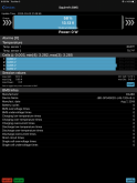
3. Then I tested the battery hook up 100A BMS that arrived this afternoon:
View attachment 4223
And low temp cut off was programmable and worked perfectly. Bluetooth connected perfectly as well. I was excited so I did a load test of 200Wh with 90-102A continious. Passed with flying colors, then pushed it passed its limit and it disconnected the loads. Heatsink stayed warm and did not heat up excessively.

I'll make a long video covering all these things and the testing methods, but I am going to go with this bms from now on. I am so tired of other bms failing. The battery hookup one is used on medical devices as well, which I need more information on.

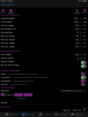
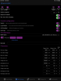
The number one most important thing to know when using this bms is that you need the proper app. The app on the website is NOT what you want. You need the "enterprise" version:
Click Here for APK of enterprise BMS program app

Send it to your phone with an email (not gmail), then install in on your phone, then connect to bms.

Then go to parameter settings and change the low temp charging cut off to 2 degrees Celsius. Then the reconnect voltage to 5 degrees Celsius.

You can buy this bms by clicking here (my affiliate link) and the coupon code is "SOLAR" for 10% off. I am going to get a 8s model and build a big system with it. I like this bms a lot, so will be testing it like crazy. I also will make a DIY video on how to use it in the next couple days (possibly tomorrow if I get enough sleep tonight).

Biggest downside of this bms is 2x 10 gauge wires at P- and B-. But it has a hole and solder tabs for adding more wires.

Just wanted you guys to know about all this before you waste your money on the first 2 bms. I wasted $150 on those bms and they were a total rip off. The new bms seems to kick butt, so videos to come. :)
is there an ios version of the app
 
Thanks Sarge. The ios version is substantially different from the one suggested by Will. At this juncture I am going to ask BatteryConnect to take back the 2 BMS units I bought. There are just too many issues with undersize wire and one reason I am adding Lithium is for the high amp draws of AC, microwave, etc. I'll just take my chance without BMS and let my charge controller and inverter handle the Low/High voltage dropout. Living in Florida the temperature senser is not that important. I will do some cell balancing from time to time to keep the batteries healthy.

Thanks for your help.
I haven't watched it again, so I don't know if this video will help you or if it would work with these BMSs.......

 
Quick question from a newbie. I have decided to jump in and built a 200ah battery pack using everything from Will’s $555 video for use in our 5th wheel trailer Instead of buying the Battleborn batteries. I did upgrade to the 4S 120a BMS And seem to have gotten everything put together and working. I downloaded the Xiaoxiang BMS app for my iPad/ iPhone, paid the $6 upgrade, and it instantly connected and works perfectly. My question is about the app and the parameter settings I should use for these batteries. The app has clearly been updated to a newer version, which is why I’m a bit lost as it does not look like the one Will was adjusting. I did figure out how to change and save the ‘designated capacity’ to 200k mAh, but that’s about all I know. If somebody who knows these LiFEPO4 battery parameters could please help me adjust whatever other parameters need adjusting I’d really appreciate it. It should be as simple as changing the numbers, clicking ‘save configuratio’ button then clicking the ‘BMS write’ button. I hope !! I’ll include photos of what the updated app screens look like and it’s current default settings. Thank you much
 

Attachments

  • 85F6712D-EF99-4F5E-B0C0-69333F0B0273.png
    85F6712D-EF99-4F5E-B0C0-69333F0B0273.png
    211.6 KB · Views: 28
  • 4A7AA665-B69C-4592-B9DD-1D0DE86A270C.png
    4A7AA665-B69C-4592-B9DD-1D0DE86A270C.png
    178.8 KB · Views: 28
  • BB56640B-2B5C-47DD-8202-9DFDD9808D6F.png
    BB56640B-2B5C-47DD-8202-9DFDD9808D6F.png
    175.9 KB · Views: 26
Back
Top