


You are using an out of date browser. It may not display this or other websites correctly.
You should upgrade or use an alternative browser.
You should upgrade or use an alternative browser.
Finally found a LiFePO4 BMS with Low-temp Charging Protection
- Thread starter Will Prowse
- Start date
Bob B
Emperor Of Solar
- Joined
- Sep 21, 2019
- Messages
- 9,165
@SCClockDr ...;.. ETC here as well. Hope you have following seas.
SCClockDr
Solar Enthusiast
Thanks, fair winds & calm seas to you as well.@SCClockDr ...;.. ETC here as well. Hope you have following seas.
Wonder if you guys could assist.
I purchased a 8S Lifepo4 100A unit from LLT directly and it was delivered a few weeks ago and it didn't come with any documentation so after getting no response (email/phone/skype) from them I decided to attempt to connect it together after checking out Will's video although the unit was a bit different to the one he had.
I only plugged in the balance lead connector and tried to connect to the BMS using the app when I noticed that the balance lead connector was getting warm so I unplug it and checked the wiring which all seemed fine so plugged it back in and connected the blue cable (P-)
Firstly I noticed that there is no voltage on the black cable (C-) and after connecting using the app I could communicate with the BMS and the info I was getting didn't make sense.
The app was showing 10 cells instead of 8 (see attached picture) as well as it seemed to be configured for LIFE indicating voltage of 4.2V.
In addition I see that the build date is 2016-03-08.
I have emailed the support email but I guess they are on chinese new year break.
Any ideas on what went wrong or how it can be fixed ?
Attachments


@Will Prowse , is it possible to hook up a second temperature sensor to this BMS? I fear if I were to leave the battery in really cold weather for a while, when the weather finally warms up, the outside (where the sensor is usually kept) will warm up before the inside of the pack and the BMS will allow the charger to start charging while part of the batteries are still too cold. I have also thought, if I put the sensor in the middle of the pack, I would have an opposite situation when the weather starts getting cold. Maybe I am just putting too much thought into this and maybe it will be just fine.
Thanks for any information you give me.
PS, would this BMS make for a good drop in replacement for an RV? Or, would I need to change my charger? (It is just a standard charger that comes with RVs I don't have any solar yet) thanks again
Thanks for any information you give me.
PS, would this BMS make for a good drop in replacement for an RV? Or, would I need to change my charger? (It is just a standard charger that comes with RVs I don't have any solar yet) thanks again
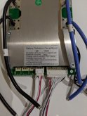
Looks like the balance cable is not installed correctly. Can you take a picture of that? each lead going out to the individual cellsWonder if you guys could assist.
I purchased a 8S Lifepo4 100A unit from LLT directly and it was delivered a few weeks ago and it didn't come with any documentation so after getting no response (email/phone/skype) from them I decided to attempt to connect it together after checking out Will's video although the unit was a bit different to the one he had.
I only plugged in the balance lead connector and tried to connect to the BMS using the app when I noticed that the balance lead connector was getting warm so I unplug it and checked the wiring which all seemed fine so plugged it back in and connected the blue cable (P-)
Firstly I noticed that there is no voltage on the black cable (C-) and after connecting using the app I could communicate with the BMS and the info I was getting didn't make sense.
The app was showing 10 cells instead of 8 (see attached picture) as well as it seemed to be configured for LIFE indicating voltage of 4.2V.
In addition I see that the build date is 2016-03-08.
I have emailed the support email but I guess they are on chinese new year break.
Any ideas on what went wrong or how it can be fixed ?
I actually burned one up yesterday because two of my cells in a large pack were swapped. I am so mad. Its the most common way to destroy these circuits.
Just program the recovery temperature to a higher temperature and you wont have to worry at all@Will Prowse , is it possible to hook up a second temperature sensor to this BMS? I fear if I were to leave the battery in really cold weather for a while, when the weather finally warms up, the outside (where the sensor is usually kept) will warm up before the inside of the pack and the BMS will allow the charger to start charging while part of the batteries are still too cold. I have also thought, if I put the sensor in the middle of the pack, I would have an opposite situation when the weather starts getting cold. Maybe I am just putting too much thought into this and maybe it will be just fine.
Thanks for any information you give me.
PS, would this BMS make for a good drop in replacement for an RV? Or, would I need to change my charger? (It is just a standard charger that comes with RVs I don't have any solar yet) thanks again
Pretty much every BMS on the market will prevent overcharging/low voltage/over current etc. It is implied that they all have this feature. If it didn't, it would not be mentioned here, I promise. Can someone show me a BMS that does not have this feature? That's what I would like to see because I have never seen one.Does the BMS prevent overcharging?
I have seen people mention "turning off the bms to save power". This is a non-issue and no one should ever do this. The power consumption of a bms is VERY tiny. And if it hit low voltage disconnect voltage, most bms will use even less. The whole point of a bms is to protect a battery. It has been thought out this way for years.
sajjen
New Member
If anyone has a system where they worry about a situation where the system would be sitting without charge for long times, just put the low capacity disconnect of loads a little bit higher. An amp hour is not that much for your loads, but can sustain the average BMS for a very long time.I have seen people mention "turning off the bms to save power". This is a non-issue and no one should ever do this. The power consumption of a bms is VERY tiny. And if it hit low voltage disconnect voltage, most bms will use even less. The whole point of a bms is to protect a battery. It has been thought out this way for years.
Looks like the balance cable is not installed correctly. Can you take a picture of that? each lead going out to the individual cells
I actually burned one up yesterday because two of my cells in a large pack were swapped. I am so mad. Its the most common way to destroy these circuits.
Here is the connector below :

offgriddle
"FOREVER BEGINNING"
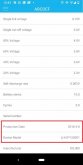
Important info. Ty.Spent the last few days and tonight testing BMS:
1. The "new" daly LiFePO4 BMS (that states in the data sheet that it has low temp charging protection) does not have low temp charging protection. And yes, it has a temp sensor attached. This disappointed me big time. Video to come.
2. Next, I programmed/tested this BMS for a couple of days:
View attachment 4222
And it failed. App would crash. Default low temp cut off was -5 degrees C. No manual and very difficult to work with. Had a lot of issues with it. Will cover every downside in my upcoming video. Avoid this BMS.
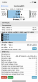
3. Then I tested the battery hook up 100A BMS that arrived this afternoon:
View attachment 4223
And low temp cut off was programmable and worked perfectly. Bluetooth connected perfectly as well. I was excited so I did a load test of 200Wh with 90-102A continious. Passed with flying colors, then pushed it passed its limit and it disconnected the loads. Heatsink stayed warm and did not heat up excessively.
I'll make a long video covering all these things and the testing methods, but I am going to go with this bms from now on. I am so tired of other bms failing. The battery hookup one is used on medical devices as well, which I need more information on.
The number one most important thing to know when using this bms is that you need the proper app. The app on the website is NOT what you want. You need the "enterprise" version:
Click Here for APK of enterprise BMS program app
Send it to your phone with an email (not gmail), then install in on your phone, then connect to bms.
Then go to parameter settings and change the low temp charging cut off to 2 degrees Celsius. Then the reconnect voltage to 5 degrees Celsius.
You can buy this bms by clicking here (my affiliate link) and the coupon code is "SOLAR" for 10% off. I am going to get a 8s model and build a big system with it. I like this bms a lot, so will be testing it like crazy. I also will make a DIY video on how to use it in the next couple days (possibly tomorrow if I get enough sleep tonight).
Biggest downside of this bms is 2x 10 gauge wires at P- and B-. But it has a hole and solder tabs for adding more wires.
Just wanted you guys to know about all this before you waste your money on the first 2 bms. I wasted $150 on those bms and they were a total rip off. The new bms seems to kick butt, so videos to come.")
We need to see each wire and its cell to see if it is wired correctly
@Will Prowse would this BMS be sufficient to create a drop in replacement for my camping trailer? I still have the stock charger converter that is designed for lead acid batteries. I don't have any solar panels yet.
Last edited:
We need to see each wire and its cell to see if it is wired correctly
Sorry not the best picture

You only become the path to ground if the system has an EARTH ground. Many DC systems do not - I.e. boats, protable power systems to name a few@SCClockDr .... I understand what you are saying .... It's just that when I studied electricity / electronics many years ago. One of the basic rules was to never switch the ground wire.
If you get used to doing that and then do it in an AC circuit or a high voltage DC circuit ...it could get you killed ....If you touch a device that has the common shut off ... you become the path to ground.
bostonbuzz
New Member
- Joined
- Jan 13, 2020
- Messages
- 52
@Will Prowse I purchased 2 of the 120A version of this BMS for a 2 x 12v x 100ah LIFPO4 setup (no LA battery). FYI it comes with 3 tinned 10g wires on each side (good for 90A, or 180A for two according to some charts I see). I don't like that the wires are soldered, since marine applications (a sailboat with a diesel engine) dictate a mechanical connection, but I think it will work. My main load is ~180Amp engine starter for 3-5 seconds and basically 1A otherwise. It should be juuuuuuust fine I hope.
My issue is that I'm relying on the BMS to do over/under voltage cutoff and temperature cutoff. Is this wise, or should I have some sort of higher rated voltage relay separately monitoring this? I have ordered the following:
1. Victron MPPT solar charger programmed for LIFEPO4 that will be connected at all times and cutoff most loads under a certain voltage,
2. A 110V Victron charger programmed for LIFEPO4 that will only be used with a gas generator when the batteries are dead, and
3. A Balmar MC-614 alternator regulator connected to my old modified 51A alternator which will monitor battery and alternator temperature - also programmed for LIFEPO4.
If any of these components stop working correctly can I rely on the BMS to cutoff power to the batteries, or should I get some more components to wire in? If so, why? I already have my chargers set up to operate correctly, and the BMS is redundant in a way. I just hear that the BMS cutoff is just for "emergencys." Is this true?
Victon system has separate modules for BMS and "battery protect" for their lithium batteries - why? Battleborn doesn't seem to require that, just relying on the internal BMS.
Bob B
Emperor Of Solar
- Joined
- Sep 21, 2019
- Messages
- 9,165
Doesn't change the fact that switching the negative is the only good practice. Why switch the common and hope there is no other patch to ground ... maybe even thru another piece of equipment.You only become the path to ground if the system has an EARTH ground. Many DC systems do not - I.e. boats, protable power systems to name a few
Pierre
Somewhere down South
- Joined
- Dec 21, 2019
- Messages
- 1,144
Hi Will , move to Cape Town , South Africa and you will not have a "low temp" problem8s not available yet. Tom said he is still waiting for that shipment. Tom and I were messing with it last night and testing every aspect of this bms. We have been trying out various bms for months now. We really though the daly would have the low temp cut off on the new model with the temp sensor.
And 16s model, I am not sure about. You could use 2x 8s models in series for 16s. That would work.
Agree best practice is to switch the "hot", but pointing out that not all systems have an "earth" ground - And most BMS interrupt the negative side for over/under voltage etc.Doesn't change the fact that switching the negative is the only good practice. Why switch the common and hope there is no other patch to ground ... maybe even thru another piece of equipment.
@boboxx I see that you have confirmed that the 120amp version also has the adjustable low temp cutoff, which of those two sites did you order it from? I have looked at both of them and there is more than one option for a 120amp lifepo4 BMS, which one specifically did you order? How long did it take for you to get it?
Thanks
Thanks
it looks like there is an iPhone apps well, here https://apps.apple.com/nz/app/xiaoxiang-bms/id1375405426.
No idea if it works, still waiting for the BMS to
No idea if it works, still waiting for the BMS to
boboxx
New Member
@Waspvl1 I ordered from aliexpress: https://www.aliexpress.com/item/32858179124.html
But from what I can see it's the same "official" supplier. It took about 3 weeks to get here in Canada.
The model I ordered was "4SLFP120A UARTRS485" I have plan to integrate it with a DIY monitor in the camper van so I will be using the RS485
The unit came with a BT dongle that connects to RS-2332 (standard uart)
Last edited:
boboxx
New Member
@matthewnz Yes it works fine for the display, I haven't bought the pro version as I don't need to change any of the parameter from it.
Attachments
MrNatural22
?SW sunshine =⚡️⚡️lit up thru the darkness✌️
@matthewnz Yes it works fine for the display, I haven't bought the pro version as I don't need to change any of the parameter from it.
I am also using the $6 iOS pro version. I see on yours it shows 1 cycle. Was that a full cycle of the battery? Because I have only gone down maybe 50-60% and there was no cycle count showing? It seems to only count full cycles, maybe down to 80% or more? That is what the parameters show currently for cycle capacity. Or do you set cycle capacity on the parameters to your estimated normal level of discharge?
Similar threads
- Replies
- 4
- Views
- 352
- Replies
- 3
- Views
- 325
- Replies
- 8
- Views
- 219
- Replies
- 0
- Views
- 282