diy solar

diy solar

First build, I have questions and would like to hear any suggestions.

35mm^2 (or 2 awg) single wire in free air, 256A, you come up with 513 degree C rise?

Please check again. If I look up 190A gives 90C, 60C rise, then at 380A I would expect 4x, 240C rise, 270C temperature.

I'm not sure to what extent a 9" jumper dumps heat into batteries it is bolted to.

I am inclined to cross connect all batteries, with the idea current will always be shared by two parallel wires that way.
If one cell goes bad, the other two in the 6V battery will cook and outgas. Bye by AGM!
 
Here is the math

12k/48v = 250amps
0.156 ohms/m
I figured 2m
250a^2 * 0.312 * 3600sec= 7,200,000w

Volume of copper
67.2cm^3 per wire * 2=134.4cm^3

Mass
134.4cm^3*8.96g/cm^3= 1204.544g

Energy
7200000w * 3600s = 252,720,000J

Temp rise = 252,720,000 Joules/ (1204.544g*0.385J/g C)

543 degrees C rise

If a wire fails all 250amps is through a single


Edit, i think i missed that it is 4 wires verse 2, so mass doubles, but if a string fails only 2 wires working

With all 4 wires the temp rise is 68c
 
Last edited:
It won't be 4 wires, just 2.
Normally current flows in a loop consisting of one wire out, one wire back. Current goes through cross section of 1 wire.
With 8s2p or 2p8s battery bank, there are 2 parallel wires (of the smaller size I'm using between batteries.)

But the basic problem with your calculation is it is related to energy deposited, Joules, in a mass of copper.
That is what you would consider for a pulse of current, like what happen when there is a fault, cleared shortly later by fuse or breaker.
In that case, we ignore conduction and convection, because time is short.

You used 3600 seconds, one hour. I haven't checked your math in detail, but it appears you are computing temperature rise if the wire is perfectly insulated. An upper limit on how hot it would get if my batter bank lasted one hour.

The usual ampacity calculation is steady-state temperature where power lost through insulation to ambient equals power dissipated by I^2R.

My case should be less than the temperature rise calculated by ampacity, but I don't know how much, or how long it takes to reach steady state. It is a combination of your thermal mass calculation and the heat loss calculation. I think "continuous" for ampacity calculations is something like 2 or 4 hours.

The math is similar to RC, exponential decay to final value. Convection may make it a bit more complicated. I would just use thermal resistance (from ampacity tables) and thermal "capacitance" as you calculated it.

I see what you mean, my method is fine for sub second fuse blows but I need to adjust for longer times.

I was only calculating within your bank so 4 by 2 awg would seem to apply.

My math was for 1awg.

I'll draw a picture and redo calculation for the wire with and without the box wires at each battery.


Gut feeling is your serial wire will be as big as the load wires to the inverters. Then the parallel wires can be smaller. So if a single battery drops out everything carries on and you still have full capacity/volts minus 1 battery. What size are your uplink wires?

Cost a bit in wire and fuses but you keep most of the energy available.

And I am doing this more for my understanding than anything else, not to give advice to you.

Any chance you know the resistance in your batteries?
 
Data sheet might say something about the batteries, haven't looked lately.

I think current goes through two wires, one per string. Cross-connects don't change that to 4 in parallel, only steals current from one string to go through other battery.

I'd like to use 2/0 to the inverter, likely one will be SI 6048US but other is 5048US with smaller dual lugs (maybe I can replace those.)
At the moment I have some cut jumper cables, 4 or 6 gauge, just so SI can float the batteries.

Series wires same 2/0 would be good, but the 24 batteries I bought came with 35mm^2 jumpers, enough to series and cross connect 2p8s. I figure they are sufficient so long as current reasonably splits. And I've figured out that if one battery gives up the ghost, cross-tie means current is still split between two wires. Having fuses in crosslinks defeats that, and crowds all current into one wire.

So only issue is what happens if bank turns into 2p7s + 1 battery. It will drain the one battery to 100% DoD, then charge it back up in reverse polarity. But I'm pretty sure voltage would drop to 42-6 = 36V before then, and inverter will shut off. Charging is set for 0.2C, so single battery would experience 0.4C. Discharging would drop single battery low faster, and pack voltage won't go too low until the one is severely over-discharged.

Primary issue is safety, how much outgassing & swelling. Battery temperature sensor of course will be on an unabused battery.
 
Can you make a Y cable, 2/0 to dual 1 awg? Split just prior to the inverter and just use 1awg-2/0-1awg with a bolt through and heat shrink over it? I don't really like this sort of thing but should be ok if done with lock washers and no-ox-id.

It seems like short of wiring it all with 2/0 the simplest would be to just fuse between the battery string and inverter and let it go offline if a battery shorts .

If you used 2/0 all along it and made 8 parallel packs then z-wired each pack in you could fuse all batteries and if one died the rest would keep going.
 
For the moment the pack is 8s2p, and kept at float.
Of the 24 batteries, I selected 16 all the same voltage. (Several lower ones I charged up to balance before assembling as 8s for another system.

I was surprised that after charging 8s2p all the way up, two batteries were noticeably higher voltage than the rest. Could mean lower capacity. Maybe two others I used in other string would be better match, but don't know which.)

The 2p8s bank I intend to diagonally connect (as I have the 8s2p). I think this is an alternate to using a "Y" cable, and also perfectly balances them.

Oh, you meant "Y" cable to inverter's dual lugs. That is what I did when I first hooked up SI 5048US with 2/0 cable. I just unraveled end and used as "Y". For the moment I have smaller cable in this new system. Think I'll look into changing lugs.

My plan for new system is 2p8s bank, 400A fuse in holder with dual lugs, 2x 2/0 cable to 2x inverters (each having internal breaker suitable for 2/0). The 400A fuse is only for catastrophic shorts, where 2/0 is sufficient to fast blow. Otherwise this is basically a feeder tap protected by breaker at far end.

My other system with 4x SI is similar, 2x 350A fuses at battery for catastrophic shorts, 4x 2/0 cable to 4x inverters.
 
So do you fuse each of the 4 x 2/0 cables? Or just use the breakers in the inverters?

I thought when making strings of batteries the first thing to do was fully charge all batteries?

Another question, with a string of 8 series and 2 parallel seems like it is simple to monitor each battery.

With 2 parallel 8 series, how can you tell the state of the parallel set? They would both read the same voltage. I suppose you could use a clamp meter to see if one was producing more current than the other and infer a condition from that?
 
Yeah, I probably should have fully charged each 6V battery. Their voltages indicated reasonable SoC and were identical voltage to 3 decimal places. I don't have much in the way of 6V sources. More at 12V, including an Outback SCC. I went through many steps trying to balance the remaining 8x 6V 250Ah batteries before putting in another system, and they also diverged when fully charged on SI. That was after being fully charged in 12V 2s configurations.

I just rely on breakers in the inverters. I figure protecting against overload at far end is fine.
Oversize fuse at near end won't blow for overload, will blow fast for a short.

With 2p8s, pairs of batteries are in parallel, can't be checked independently. If either acts up, their voltage will get out of whack from others in series.

True, clamp ammeter could distinguish. Around cross-tie to measure imbalance, or around series & cross tie to measure what goes into battery.

My assumption is they are held in lock step until they start to degrade. Holding pairs at same voltage should avoid one walking down in SoC and condition relative to the other. But I don't have that much experience with batteries. These didn't cost me much money because used, but new would be about 5x the price. Maybe a balancer would be a good investment.
 
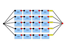
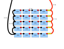
I just went with 48V 200A terminal block fuses for the positive end of each string (4 strings total). And a 48V 250A breaker going into the inverter. In regards to the pics I attached: I know you need to keep cable lengths the same. But is it ok to do all the series connections shorter (6 inches)?? And all the parallel connections 12 inches?? And which of those 2 pictures is the better way of doing it? Bringing all the parrallel connections back to a central bus bar, then out of the bus bar to inverter... or using parallel jumpers to the next string, then taking the mains out of each opposite end of the bank to the inverter? I know this preschool basics compared to the in depth exchanges you guys have been having, but a lot of that lingo is still foreign to me at this time. I now have all components (I think), Hopefully will have time to start building it next week. @timselectric @Hedges @OffGridForGood @robbob2112

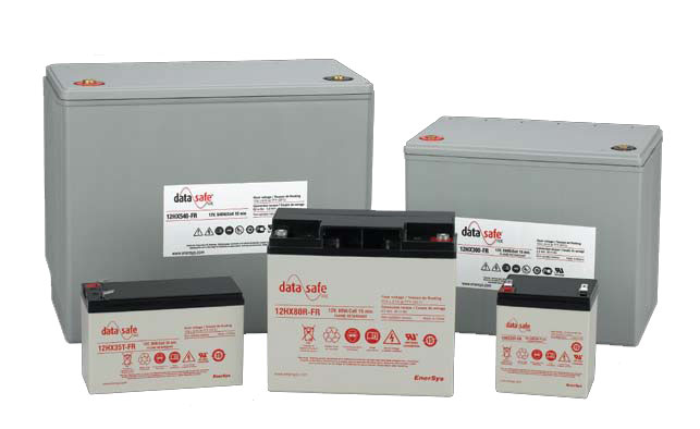
Also, I acquired more batteries that are close to the specs of the (12) FIAMM 12 FLX 500 I already have. These are:
If I wanted to add 1 more string. Should I just add these 4 DataSafe batteries in a new string at the bottom of the bank? Or mix 1 into each of the other strings of the FIAMM batteries? The first option definitely seems like the most logical. What do you guys think? I have 10 of these Datasafe in case I need backups.

And 1 last thing lol... I want to first get an even charge on all batteries, correct? Let me just make sure this is right. I will hook the 12 FIAMMS together in a long parallel train. Then take my 15A 12V battery charger and charge like an hour on one end, and move it in increments down to the other end until I get a full even charge on all? Then let them sit for several hours still hooked up to further balance the voltage?

Thanks again guys.
 

Attachments

  • 48V Battery Bank.jpg
    48V Battery Bank.jpg
    256.4 KB · Views: 6
  • 48V Battery Bank.jpg
    48V Battery Bank.jpg
    271.5 KB · Views: 6
For the left drawing, all that matter is sum of cable lengths through first string equals sum of cable lengths through second string equals ...

The cables to negative side of inverter don't need to be same length as cables to positive side.

Just make all negative cables one length, all series jumper cables between batteries a different length, all positive cables yet another length.
But it is also OK if positive plus negative are same length for each string. e.g. gather all 5 negative cables to a tie point near bottom left, all positive to a time point near top right.

For the right drawing, it is less than perfectly balanced. Although the wire distance through each string to the inverter, sum of positive and negative wires, is the same, the voltage drops won't be identical because some parallel jumper cables carry the current from multiple batteries, others only from one. This approach of tapping from diagonal corners works for two parallel strings (4s2p).

If you have 4 strings (4s4p), a similar approach works. Two sets of 4s2p, which are then connected with longer parallel jumpers to make 4s4p.

For 5 strings (4s5p) there is no perfectly matched way to wire it like that. probably close enough for lithium, but for lead-acid we want to match battery charging perfectly.

For 5 strings, maybe better to use scheme on the left. Could join the wires at a busbar, or at a Polaris tap.
 
See, I've been reading about balancing different strings. For 4 strings connecting at the 1/2 way point between string 1 & 2 and the 1/2 way point between string 3 & 4 is perfect. But that only applies to lithium. The higher internal resistance of SLA/AGM/FLA changes that. I don't suppose you know the internal resistance of your type battery? Might be a fun exercise to recalculate that for them.
 
See, I've been reading about balancing different strings. For 4 strings connecting at the 1/2 way point between string 1 & 2 and the 1/2 way point between string 3 & 4 is perfect. But that only applies to lithium. The higher internal resistance of SLA/AGM/FLA changes that. I don't suppose you know the internal resistance of your type battery? Might be a fun exercise to recalculate that for them.
The Datasafe's say
  • Internal Resistance (mΩ): 3
Can seem to find it on the FIAMM on this pdf
 
For the left drawing, all that matter is sum of cable lengths through first string equals sum of cable lengths through second string equals ...

The cables to negative side of inverter don't need to be same length as cables to positive side.

Just make all negative cables one length, all series jumper cables between batteries a different length, all positive cables yet another length.
But it is also OK if positive plus negative are same length for each string. e.g. gather all 5 negative cables to a tie point near bottom left, all positive to a time point near top right.

For the right drawing, it is less than perfectly balanced. Although the wire distance through each string to the inverter, sum of positive and negative wires, is the same, the voltage drops won't be identical because some parallel jumper cables carry the current from multiple batteries, others only from one. This approach of tapping from diagonal corners works for two parallel strings (4s2p).

If you have 4 strings (4s4p), a similar approach works. Two sets of 4s2p, which are then connected with longer parallel jumpers to make 4s4p.

For 5 strings (4s5p) there is no perfectly matched way to wire it like that. probably close enough for lithium, but for lead-acid we want to match battery charging perfectly.

For 5 strings, maybe better to use scheme on the left. Could join the wires at a busbar, or at a Polaris tap.
Thank you, from what you said I will go with the left drawing with the battery bar. But I will most likely have to make some 18" cables to make that stretch from the strings on the outside of the bank.
 
What do you think of Polaris as Busbar, my recent epiphany?

Selecting a large enough connector, you can slide insulated cable through the hole. Strip about 1" of insulation in the middle, and tighten set screw on it.

A 3-hole Polaris would then have 6 wire ends hanging out. Enough for 5 batteries tied to one fuse/breaker/inverter.

Oh, is Polaris OK for fine strand welding/battery cable? Or just coarse strand typical for facility wire?
 
Polaris connectors are a set screw type connection.
If the strands are super fine, they could be damaged.
All of my "bus bars" are standard (set screw) multi port wire connectors.
Basically the same thing as the Polaris, without the rubber covering.
 
Aside:
For 5 strings (4s5p) there is no perfectly matched way to wire it like that. probably close enough for lithium,
And for seven packs not all matched in capacity, connected to large bus bars, with the main tap to the inverters fed from the middle of each bus, the only way to get battery balance is to play with wire lengths and ga. (assuming you have no life at all outside of playing with ESS balance) and adjust them a bit at a time and watch how the balance strays and then adjust a bit more day after day for weeks on end...eventually you get to 'close enough' and call it done.
 
Back
Top