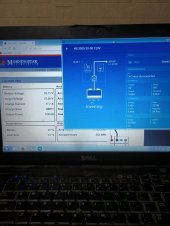
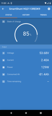
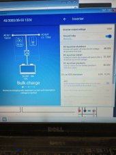
MPII as in Multiplus 2? Do you have a Victron smart shunt? Multiplus need a shunt to properly measure SOC.Getting ssoc from Victron connect via mk3 to MPII
Also voltage based SOC is pointless.
Watts don’t disappear, either it’s being used, going into the battery, or burning something down.