diy solar

diy solar

Future battery upgrades/replacements

With my next bunch of them, I may add in the 6 missing batteries... I’m a little worried I won’t have an exact MAh match though... I don’t want to pull the batteries out and test them... idk... I think the extra 55Wh would be worth it...

Yes. I think those missing batteries will make a difference. How are you going to put them on? Soldering or will you use a welder?
 
I have been tinkering with using a solenoid and a momentary switch with copper nails and a battery...

I’m too cheap to buy a regulated spot welder.
 
I couldn’t find any info on the charging inside... is there a mppt controller in there? Can I hook panels directly to it? I think since it states 12-24V then a 12V (17V ISH) panel directly connected should work.
 
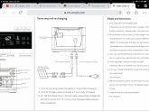
Actually, I found the manual online...
19172EA6-E82B-4B0C-B74B-C1DA257F63F4.png
So, it will work directly off a panel, but oddly it charges slower, than connected to a cigarette lighter socket...
 
I have been tinkering with using a solenoid and a momentary switch with copper nails and a battery...

I’m too cheap to buy a regulated spot welder.

Share some more information. I have done soldering and it was a pain in the butt and I don't think I want to go through it again. Too time consuming. Well.... I guess that this needs 6 batteries that it isn't so bad.
 
I couldn’t find any info on the charging inside... is there a mppt controller in there? Can I hook panels directly to it? I think since it states 12-24V then a 12V (17V ISH) panel directly connected should work.

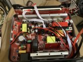
It has a built in MPPT solar charge controller instead of PWM that you see in devices at a similar price point. It is part of the mainboard inside that has the inverter on it. The side with the PCB with white LED standing up vertically is the inverter side. The side with the two thick wires screwed onto the board. The MPPT is on the opposite side. If you look on the original BMS, there are two sets of wires (red and black) and also the ribbon cable. The thicker ones are the output and go to the inverter with the screws. The thinner ones go to the MPPT. Those go to a XT-60 connector.
 
Share some more information. I have done soldering and it was a pain in the butt and I don't think I want to go through it again. Too time consuming. Well.... I guess that this needs 6 batteries that it isn't so bad.
 
Odd that it recharges in 6 hours on AC or 12v lighter cord, but takes 14 hours on solar...

I think that is if you use the solar panel they listed. My unit definitely doesn't take 14 hours on solar. Guesstimate around 5 hours if the battery is dead. (9.5 volts)

9.4 volts is when it starts beeping at you. I have taken it down to 9.0 volts. Turn off the unit and wait a few minutes.... turn it back on and it shows 9.5 volts.
Yeah, with mine connected to26v solar input, it fills up in about 3 hours from 10.8V. Looks like it pulls around 100 watts.
 

Consideration...
 
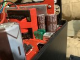
I just got 5 more, and the first one I opened has blown fuses in it...image.jpg
The batteries are at 9.01V, and the BMS is bad... I’m hoping the main board is ok...

fingers crossed.
 
I just got 5 more, and the first one I opened has blown fuses in it...View attachment 19500
The batteries are at 9.01V, and the BMS is bad... I’m hoping the main board is ok...

fingers crossed.


I feel there are some flaws with these units. One is going to be the cooling. When charging or in use, the battery area will get very warm. There is really no way to get any air to the bottom compartment. Seems all the air from the fans are used to cool the mainboard/inverter. Another thing is that I see most of my problems show up when charging with AC. I have noticed that besides the added heat that lots of times it will overcharge. I have had one unit charge up to 13.2 volts. Inverter would not turn on. DC ports not work. I had to use test leads clamped to the screws for the inverter and had a different device pull the power until the battery pack went down to 12.4 volts and everything was fine after that. Never had that happen when charging using the DC input with solar. So I think the problem why the BMS's keep getting burned out is because of this issue. Heat and AC charging.
 
Ok, I have worked on my next one from the new batch.
Fuses were fine... dc charging isn't working. Ac seems to, but doesn't charge actually.
Also, the inverter isn't working.
Ugh... i got a dud, and one that is a big phone bank...
I hope the next 3 work ok... I'm just buying batteries so far this round.
 
A new version!

The latest one I opened up has a different failure, and a different control board...

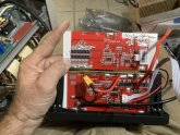
This one has 3 red/black pairs of wires, one of which is soldered to the BMS...

And the cells are depleted to 5ish V... but the BMS has not failed I don’t think... I get readings on the P- terminal...

Nope, this one has a bad BMS also, but the fets are on the positive side instead of the negative side.
 

Attachments

  • image.jpg
    image.jpg
    102.3 KB · Views: 10
  • image.jpg
    image.jpg
    87.2 KB · Views: 10
Last edited:
Ok, I opened the last two units I got this time...

One has a fully charged bank, and a perfect functioning BMS, and the other has nothing wrong with it at all... So far.

I have tested BMS output, and the display is fine, and all outputs operate correctly. I’m testing the ac charging now, and will test dc charging tomorrow... but so far it looks fine to me.
 
A new version!

The latest one I opened up has a different failure, and a different control board...

This one has 3 red/black pairs of wires, one of which is soldered to the BMS...

And the cells are depleted to 5ish V... but the BMS has not failed I don’t think... I get readings on the P- terminal...

Nope, this one has a bad BMS also, but the fets are on the positive side instead of the negative side.


Wow.... I haven't seen one with that setup. All of mine have shown up with the two power connectors and the regular BMS. So would you say this new design is better or still crap? Would you also think it is better to go with a different BMS or is the original one better?
 
Wow.... I haven't seen one with that setup. All of mine have shown up with the two power connectors and the regular BMS. So would you say this new design is better or still crap? Would you also think it is better to go with a different BMS or is the original one better?
I am tinkering with it right now... there is the new header, and an additional component, looks like a capacitor, or a relay... not sure yet.
The BMS is shot, but it looks like I can get the cells charged with AC. The solar only put out 2 watts... so, something is dead there... I will install a new BMS... I’m just wondering what the wires feed... all the boards have the pins for the cable, and the component, so it may actually be an older design...

I’m stoked I got two good BMS packs, and one perfect unit... nothing wrong so far with it.
 
The cells were down to 5ish volts, I have had them AC charging about 30 minutes, and they got a little warm taking around 85 watts... I shut off the AC charging and hooked solar back up, and it is taking a little over 6 watts now... maybe the BMS is throttling the solar charging until the bank reaches 9v? At 5ish volts, I couldn’t get in 2 watts, now that AC has them up to 7ish volts, I’m getting in 6 watts... I will check them in the morning, and see what voltage and wattage is going in...
 
Back
Top