diy solar

diy solar

Gauging Busbars Bus bars DIY

Carly

New Member
Joined
Dec 29, 2019
Messages
86
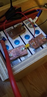
How do you gauge your busbars for your battery packs? They come in thicknesses from just over a millimeter to a few mm. Some are aluminum, most are copper. They can be either naked or nickel-plated, bare or with heat shrink. Some are solid, others are laminated. I ordered some 1" x 1/8" C100 copper flat bar to make my own, but wonder if that was necessary.
busbar.JPGbusbar2.JPGbusbars3.JPGbusbar4.JPG
 
thickness x width gives you the capability in AMPS.
the rule is 1mm2 for 1.2A in copper or 0.75A for aluminium.
so a busbar that is 2mm thick by 20mm wide is 40mm2 so 48A in copper.
Busbar for battery are usually very short, so you do not need to strictly follow it.
I would not stack several thin busbar since the contact is also important.
to get good contact you should have mirror finish on both battery and busbar and surface must be as flat as possible and you need a screw
with large head or use washer (if possible in copper)
in reality you are far from this, so contact is only partial.
to overcome the problem, there is several workaround.
get slotted hole and/or apply a layer of tin (some busbar are totally tinned for oxydation protection, but that works only for copper).
make sure you use tin without lead, cheap electronic solder can contain up to 60% lead.
Copper oxydize , but the layer is conductive and soft so it is not critical.
Oxydized Aluminum gives a very hard non-conductive layer, so Aluminium is not really good for busbar.
 
Last edited:
Thank you, @nosys70. My DIY copper flat bars will be 3.17 mm. Assuming I polish them and the terminals flat, do you think using NO-OX would be useful? It is conductive and also helps prevent corrosion. I am in an arid area, but also mobile. Thank you for the feedback.
 
I wish you a good day!
I received 4 x battery cells, Lifepo4 CALB 3,2V 200Ah, from Aliexpress today. The battery cells came with copper busbars.
The busbar profile is as shown in the images above with a yellow shrink sleeve. The busbar is made of three thin layers, the entire thickness is 1,45mm.
Busbar cross section is calculated to, 1,45mm x 21,0mm = 30,5mm2.
30mm2 equals to approx 2 AWG.
For a battery application to run 1C (200Amp) I'd consider the cross-section of the busbar as borderline according to electrical standarts, not robust.
Any comments from your side?
thanks!
 
@Carly No-Ox, Ox-Guard are a very very good idea to use especially with mixed metals. The trick is, not to slobber it on, wipe it on and leave a thin coating on the contact points and no gobs. (keep it tidy). You only need it on the surfaces that make contact, so the top of the cell posts only. You can also apply it to switches & shunts if you have them as well.

On my rebuild of the ShunBin mess, I used 110 Copper Bar Stock, quite a difference IMO.
TOP is the Aluminium Bus Bar that was used by ShunBin (4mm thick by 30mm wide) scrapped
Bottom is the 110 Copper I used (6.36mm thick by 38.1mm wide)


PACK-BusBars.jpg
 
if you worry for copper oxydation, just apply a layer of tin over it.
copper does not rust easy if you are in a dry place.
the NO-OX is not a good idea IMHO
especially they do not publish what it contains even in a SDS sheet that is for safety.
such product would not even enter in my company or is probably out of rule in most countries for not providing ingredients on the package.
pure joke, probably plain vaseline sold for the price of champaign, but hell, vaseline is great to prevent oxydation, so after you installed the busbar, you can apply a layer of this, it will not hurt.
 
Last edited:
For pulling 280Ah, the 1,2x rule of thumb would throw me to 20mm x 12mm busbars.... and that's MASSIVE.
Is it possible to recalculate the 1,2x rule for the short distances used in cell busbars? (aprox. 8cm, or 15cm if paralleling two cells)

Using this DC loss calculator: https://photovoltaic-software.com/solar-tools/dc-ac-drop-voltage-calculator to estimate results on a 16S2P 48V 560Ah battery, at 0.5C:
The busbars will be around 15cm each (because I'll be paralleling each two 280Ah cells), and assuming they'll be at 60ºC (under load):
If I'm doing everything right, these are the results:

For cell #1:
  • 240mm2 (12mm busbar) yields a 0,01v drop voltage with 1,80W (0,20%) power loss
  • 120mm2 ( 6mm busbar) yields a 0,02v drop voltage with 3,61W (0,40%) power loss
  • 50mm2 (2,5mm busbar) yields a 0,03v drop voltage with 8,66W (0,97%) power loss
For cell #16:
  • 240mm2 (12mm busbar) yields a 0,01v drop voltage with 1,80W (0,01%) power loss
  • 120mm2 ( 6mm busbar) yields a 0,02v drop voltage with 3,61W (0,02%) power loss
  • 50mm2 (2,5mm busbar) yields a 0,03v drop voltage with 8,66W (0,06%) power loss
Therefore, for the entire battery pack, these would be the total results/losses:

1582299072206.png


Can someone confirm if I'm doing everything right?
If so, even though the losses on a 50mm2 / 2,5mm thick busbar aren't ideal, they don't seem to be unacceptable: for a scenario were I would be pulling 14kW out of the battery, I would have:
  • A voltage drop of 0,48v (0,9%) and
  • A power loss of 138W. This heat would be dissipating across 2,4 meters of busbars.
And this 0.5C / 14kW would be a very extreme scenario. It would occur almost never, and would never last or more than 2 hours.

What do you think?
 
Last edited:
the rule is the rule, but you can calculate the resistor you get and the loss.
you could go for 30mmx6 for example.
are you sure you will use the batttery at 1C ? it means you will discharge them in 1 hour.
resistance = resistivity × length / section
but it will be very low.
even the type of copper (CU-OF or OFE or CU-ETP is not the same for example) you purchase can make a difference.
and also the fact you have annealed it (heated) or not.
Cu-ETP (Electrolytic Tough-Pitch) is a pure copper. This copper is characterised by a minimal amount of 99.90% copper and a minimal electrical conductibility of 100% IACS (International Annealed Copper Standard).
Cu-OF(Oxygen Free) is a high purity, oxygen free, non phosphorus-deoxidized copper. This pure copper has a guaranteed minimal amount of 99.95% of copper and a minimal electrical conductivity of 101% IACS (international Annealed Copper Standard)

As i said we do that everyday (putting undersized wire, but keeping as short as possible).
Even devices you purchase (a switch) are undersized to keep prices low and most of them do not even use copper when they can use something else.

Thanks for the inputs.
95% of the time I will be using my battery at under 40Ah, but I want to dimension/be safe in case I pull it to 280Ah (that's 0.5C, for a 560Ah battery).
I edited my post above, to include some estimates of what a 20mmx2,5mm would yield in this scenario.
 
that seems reasonnable.
the thing is you always have a part that is underwired.
so if you make the battery and the cable rock solid to support a lot of amps, you just pushed the problem into the inverter.
probably even the input terminals of the inverter are well undersized.
in that case you should think about fusing at an acceptable level, so you do not smoke everything.
a 80 or 100A fuse seems to be a good balance.

I'm aiming for a 300A fuse at the battery.
I can lower it quite easily, though. It's an ANL fuse on a fuse holder.
 
I am very curious about this width X thickness X 1.2 =Amps that you can pull with your bus bars.
I have a 12V DIY LiFePo4 90Ah battery and am using a homemade copper pipe bus bar (hammered the pipe flat).
I am experiencing voltage drop under load no matter what bus bars I use.
My bus bars are 57mm x 3.2mm and get EXTREMELY hot under a load of 65A.
57mm X 3.2mm X 1.2 = 217A I should be able to pull.
I have confirmed the connections are tight. Any advice? Thanks!
 
Bus bars should never be hot. Mine don't even get perceptibly above room temp at nearly 200A load. Your local metal supplier can help. Copper pipe may be too thin. Are you joining copper against copper with no intervening steel washers?
 
I have copper bus bar straight on the battery terminals with one small washer on top. I think the picture does better explanation than my words. Thanks for your help!
 

Attachments

  • 20201104_170040.jpg
    20201104_170040.jpg
    80.5 KB · Views: 87
I have copper bus bar straight on the battery terminals with one small washer on top. I think the picture does better explanation than my words. Thanks for your help!
As you can see the bus bars are pretty hefty given this is a 12V battery and I am only pulling a maximum of 1200W.
 
if you worry for copper oxydation, just apply a layer of tin over it.
copper does not rust easy if you are in a dry place.
the NO-OX is not a good idea IMHO
especially they do not publish what it contains even in a SDS sheet that is for safety.
such product would not even enter in my company or is probably out of rule in most countries for not providing ingredients on the package.
pure joke, probably plain vaseline sold for the price of champaign, but hell, vaseline is great to prevent oxydation, so after you installed the busbar, you can apply a layer of this, it will not hurt.
I was about to agree with you about insufficient info on SDS, but on second thoughts it appears to be the safest substance known to man:

"California Prop. 65 This product is not known to contain any chemicals currently listed as carcinogens or reproductive toxins."

Can't even get a cup of Starbucks coffee without being warned about the risk of getting cancer!

You may have nailed it:

 
I have copper bus bar straight on the battery terminals with one small washer on top. I think the picture does better explanation than my words. Thanks for your help!
Regarding the hammer marks: wondering if the hammered parts of the copper pipe have created inconsistent contact (some parts more in contact, some less) between the upper and lower section of pipe, which is causing the loss in current handling capacity and therefore creating heat.

Some here have used either a vice with large jaws to concentrate the compression evenly across the busbar, or have used a hydraulic press of some kind to get more consistent results.

This was going to be my response, so no need to type it again. "Flat" is not flat. Sometimes the cheap route isn't so cheap.
 
This was going to be my response, so no need to type it again. "Flat" is not flat. Sometimes the cheap route isn't so cheap.
And I'm really cheap! I love the idea of making my own whatever (why I'm here) but getting several conductors to basically cold-weld using hand tools is problematic, to say the least.

@upnorthandpersonal has done some impressive work with getting copper braid and sleeves to cooperate via cold-welding - the exact link I'm missing - but this thread has some great ideas, too: https://diysolarforum.com/threads/diy-tinned-copper-bus-bars.5370/
 
@upnorthandpersonal has done some impressive work with getting copper braid and sleeves to cooperate via cold-welding - the exact link I'm missing - but this thread has some great ideas, too: https://diysolarforum.com/threads/diy-tinned-copper-bus-bars.5370/
One of the links where I mention them, with picture: https://diysolarforum.com/threads/this-could-be-interesting.7835/page-4#post-100658

This is how the inside looks after compression: https://diysolarforum.com/threads/this-could-be-interesting.7835/post-114359
 
Given the limited clamping force from the small screws, you need something that's quite flat.

To gauge the flatness of the bus bar, mark the entire contact surface with a sharpie or blue marking compound. The glue a piece of 400 grit sandpaper to a flat surface. Glass works, but anything truly flat is fine. Make a few passes with the sandpaper on the marked surface. High and low spots will become obvious.
 
You could also do the following: get a steel washer slightly bigger than the battery contact terminal. Press it in the bus bar with a vise, making sure you press it 'in' the copper less than the height of the contact above the plastic of the battery terminal. This will give you a flat surface where it matters (the exact terminal size).
 
You could also do the following: get a steel washer slightly bigger than the battery contact terminal. Press it in the bus bar with a vise, making sure you press it 'in' the copper less than the height of the contact above the plastic of the battery terminal. This will give you a flat surface where it matters (the exact terminal size).

Adding to this excellent idea, press two washers in at the same time so the indentations are parallel.
 

diy solar

diy solar
Back
Top