diy solar

diy solar

Grid and Off-Grid Neutrals bonded to same ground ?

I will connect (or at least was planning to...) the inverter's ground to the house ground.
That's where this whole issue started with.
I suppose that my inverter does Neutral to ground bonding internally when in battery mode. Even if it doesn't, I can achieve this bond using the inverter's external relay and an AC contactor.
This isn't the issue.
The issue is that the house ground is also bonded to the house/grid Neutral, and my worries are about having 2 Neutrals (one from grid, one from inverter's NG bond) on the same ground.
Exactly what I am thinking also for my setup. Seems like everyone just puts them this way.

EDIT: On a second thought, obviously these machines work with the same neutral when ac IN is working and grid is not down.
In theory the issue happens only when grid is down. But then maybe it doesn't matter as grid is down.
 
Last edited:
I think I found an answer, or at least some proof that it's not an issue:
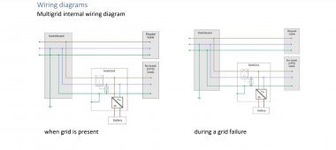
From a Victron "Multigrid" Invert manual:
Screenshot_20220905-104650_Samsung Notes.jpg

Here they show the exact use case I was talking about (well, almost... more on that later).
You have loads divided into critical and non-critical. Non-critical are powered from the grid, critical via the inverter/backup.
So by this diagram, it doesn't seem to pose an issue having the ground common to both.
Although @LeoY you may be correct that if the grid isn't there, this probably won't be a problem anyways.

But still there may be some problems:
1.
In a 3 phase system, it's not enough to disconnect the grid input (just one of three phases) from the inverter's input, as described in the diagram. That's because you still have other phases which have an N-G bond on their (usually common) Neutral.
Although I know that electricity wants to return to its source, so maybe the grid Neutral will not be affected, because it's not the source of the inverter AC.
But I'm no AC expert, so this is just a theory.
2.
Let's say that only one phase of a 3 phase AC system goes down for some reason. The 3 phases share a common neutral. Therefore, the phase that the inverter is on, could theoretically introduce currents on the grid Neutral, because if the N-G bond of the inverter.
Would this be safe for linemen working on a grid fault?
 
I think I found an answer, or at least some proof that it's not an issue:
From a Victron "Multigrid" Invert manual:
View attachment 110319

Here they show the exact use case I was talking about (well, almost... more on that later).
You have loads divided into critical and non-critical. Non-critical are powered from the grid, critical via the inverter/backup.
So by this diagram, it doesn't seem to pose an issue having the ground common to both.
Although @LeoY you may be correct that if the grid isn't there, this probably won't be a problem anyways.

But still there may be some problems:
1.
In a 3 phase system, it's not enough to disconnect the grid input (just one of three phases) from the inverter's input, as described in the diagram. That's because you still have other phases which have an N-G bond on their (usually common) Neutral.
Although I know that electricity wants to return to its source, so maybe the grid Neutral will not be affected, because it's not the source of the inverter AC.
But I'm no AC expert, so this is just a theory.
2.
Let's say that only one phase of a 3 phase AC system goes down for some reason. The 3 phases share a common neutral. Therefore, the phase that the inverter is on, could theoretically introduce currents on the grid Neutral, because if the N-G bond of the inverter.
Would this be safe for linemen working on a grid fault?
One phase of a 3 phase AC system going down is a tough scenario.
But the Victron Multigrid pic you posted pretty much clears the issue on how to wire it.
This is what we where guessing and probably stands true.
My only other concern right now is if i have to bring a seperate ground wire from the ups loads(critical loads panel) or a common ground will be sufficient and just wire the two panel grounds together.

I will probably just bring a seperate ground cable just to be on the safe side when the n/g bond during off grid time happens.
 
Last edited:
From the Victron diagram, I don't see a reason why not to wire the two panel grounds together.

Where else will you take a ground from?
Basically all grounds should be bonded together.
 
Neutral from the invertor should be bonded to PE , assuming you don’t have islanding support. If you do you’ll need a local ground rod.m
Historically many European systems did not bond neutral to PE , in fact some are specifically floating , PE merely ran to an earth rod.

Earth rods are now rare.

Your invertor will need rcbo on its outputs unless it’s feeding into the consumer box before the house RCBO.

Note GFCI is deprecated terminology as ground is not necessarily involved at all.
 
I would be very cautious about making any neutral to ground bonds that aren't in the manual.

Coming from a NEC background here, i realize other places will be different. There should only be one neutral-ground bond in a system, if you have two bonds you are basically turning all of your grounds in to a parallel path for the neutrals. If it's not in the manual, bonding the neutral and ground on the output may really mess with your inverter.

All grounds in the systems should be connected. (Even isolated grounds, like in a hospital, are still connected in one spot)
Common single earth neutral bonding is preferred absolutely. But in some cases like say your remote PV frames and support structures it may be unwarranted to run a PR wire out from the houses earth wire system. The alternative is to establish a local protective earth.

Invertors should always have ( unless In very rare specialised circumstances ) an neutral earth bond , this is often relay based whether the invertor is generating or not. All ** AC generation should in effect have neutral earth bonding when generating

( unless you don’t have a power line early to neutral bond as some countries have floating neutrals )
 
But in some cases like say your remote PV frames and support structures it may be unwarranted to run a PR wire out from the houses earth wire system.
Possibly with various system designs. I would always recommend running a ground wire with all circuit conductors. Separate structures here are required to have a ground rod at the structure (Stabilize local voltages and prevent floating) as well as a ground ran back with circuit conductors. The ground wire heading back to the inverter from a remote array allows the inverter to sense isolation issues and ground faults within the array. The equipment grounding conductor is designed to carry fault current back and facilitate tripping of the over current device.
 
Possibly with various system designs. I would always recommend running a ground wire with all circuit conductors. Separate structures here are required to have a ground rod at the structure (Stabilize local voltages and prevent floating) as well as a ground ran back with circuit conductors. The ground wire heading back to the inverter from a remote array allows the inverter to sense isolation issues and ground faults within the array. The equipment grounding conductor is designed to carry fault current back and facilitate tripping of the over current device.
But a panel is DC and is floating , it has no earth path
 
But a panel is DC and is floating , it has no earth path
Correct. With current flowing through the cells/wires/conductors. This will induce voltage on other conductors, like metal frames. So the frames and metal parts should be connected to earth (ground rod/grounding electrode) to keep potential the same so you don't get a static like shock touching them. The ground wire going back to the inverter let's the inverter know the system is still intentionally ungrounded. If a dc wire was to be smashed or wore down and comes in to contact with metal conduit, framing etc, now the system is "grounded" unintentionally and there is now a hazard from the other conductor to metal parts. You may say thats OK it's just grounded now but the electrical system should be predictable and as designed.

This isn't the case with PV panels because they have a limited short circuit current but on an AC system when the hot leg unintentionally touches a conduit or framing etc a large current will flow in the ground wire and go back to the main service where it is connected/bonded to the neutral (completes the circuit). The large current trips your over current protection and clears the fault.
 
Correct. With current flowing through the cells/wires/conductors. This will induce voltage on other conductors, like metal frames. So the frames and metal parts should be connected to earth (ground rod/grounding electrode) to keep potential the same so you don't get a static like shock touching them. The ground wire going back to the inverter let's the inverter know the system is still intentionally ungrounded. If a dc wire was to be smashed or wore down and comes in to contact with metal conduit, framing etc, now the system is "grounded" unintentionally and there is now a hazard from the other conductor to metal parts. You may say thats OK it's just grounded now but the electrical system should be predictable and as designed.

How does “ ground wire going back to the invertor “ let the invertor know anything , they don’t “ monitor “ earth bonding generally. ?
This isn't the case with PV panels because they have a limited short circuit current but on an AC system when the hot leg unintentionally touches a conduit or framing etc a large current will flow in the ground wire and go back to the main service where it is connected/bonded to the neutral (completes the circuit). The large current trips your over current protection and clears the fault.
Yes , I agree , but a local earth ground ( via a frame set in the ground or a earth rod ) will offer protection and these days inverters should have RCD type safety disconnects on their outputs so that any unintentional current path trips these. As I said use the house earthing system by preference as it’s typically these days has PME style grounding and that’s better then earth rods

But if your array is in a field , a local earth is better then nothing imho. The key with local earths is not to connect them together so that one does not become a conductor path for all other earth faults
 
How does “ ground wire going back to the invertor “ let the invertor know anything , they don’t “ monitor “ earth bonding generally. ?
Its confusing, they use "grounding" to refer to the act of bonding metal parts to the "grounding conductor" which doesnt have anything to do with the Earth yet. This is where your standards like UL 1741 come in. Inverters are required to do isolation tests upon start up. You measure resistance from the ground wire to power conductors. Your earth is not a good current path to use.

Consider a situation where your PV array is 800' away from your home. The negative PV wire has a screw in it and is now connected to all metal parts of your racking. The system works fine. How does the inverter detect this? Uses the earth to find residual current leaking? What is the resistance through the earth? Megaohms?
 
I recently did some testing and seems that just using the grid's ground/earth is not an issue, at least in my case.

I had the inverter running in battery mode. Inverter ground was connected to grid's ground. On the output I had an RCBO (RCD with built in MCB), that was N-G bonded.

I ran some loads, no issues. House RCD did not pop, and RCBO on the inverter didn't either.

I'm not sure what the outcome will be if there is a fault, but the RCBO I'm using has a lower threshold (30mA) than the house RCD, so I suppose there shouldn't be a problem.
Also, the RCBO I'm using is a type B, which also detects DC current leakage. This is important because DC current leakage can "blind" some RCDs and cause them not to see the AC leakage.
 
Back
Top