diy solar

diy solar

Growatt SPF 5000 TL HVM-P - SEPLOS 200A BMS - CANBUS?

CV350

New Member
Joined
Apr 27, 2021
Messages
68
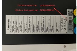
I have the above Inverter and BMS and am wondering whether my inverter actually has CANBUS communication as I have been having some problems getting it to communicate with the BMS. I have also read that many others have the same issue and it turns out that some early versions of this Growatt inverter don't have the ability to communicate over CAN (albeit that it was advertised and sold as having CANBUS) and the coms must be RS485 between the BMS and inverter. The inverter was purchased in April and when I look at the manual it also references CANBUS.

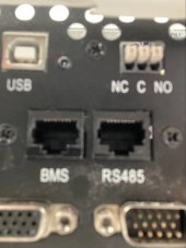
There are two ports on the bottom of the inverter (one labelled BMS and the other RS485 - see attached poor picture). This problem would only be with the inverter as I am sure the BMS has CANBUS protocol.

Has anyone got this inverter with the same labelling on the port and if so is it supporting CANBUS? I have tried asking Growatt but the response is so slowwwww. Thxs.
 

Attachments

  • IMG_8760.jpg
    IMG_8760.jpg
    209.7 KB · Views: 20
Thats was also my concern. But then I have also seen other pictures of this inverter with just the one RS485 port and a USB slot. So thats the part that I am uncertain on.
 
View attachment 75568
It seems if the inverter support CANBUS, it will indicate like in the picture.
Out of interest Brady is that inverter a HVM-P or a HVM-WPV-P. My supplier says the current and updated version of the first model still has no CANbus port. Only the HVM-WPV-P has CANbus but they are looking at a chart thats related to specific battery OEM packs not DIY. Seplos claims their BMS for DIY can communicate with "Growatt".
 
Last edited:
Received the following graphic from Growatt today.

The latest version of SPF5000TL HVM-P is the model ending with P/N 102 and has CANbus as well as RS485 coms. Seplos advertise that they have CANbus on their BMS and compatibility to communicate with Growatt inverters. I will know soon.
 

Attachments

  • Catch44BA.jpg
    Catch44BA.jpg
    320.3 KB · Views: 57
Received the following graphic from Growatt today.

The latest version of SPF5000TL HVM-P is the model ending with P/N 102 and has CANbus as well as RS485 coms. Seplos advertise that they have CANbus on their BMS and compatibility to communicate with Growatt inverters. I will know soon.
Anything further on this yet? Having same issue
 
I have received the inverter but I haven't been up to the property to instal it yet. Will do that this coming week and let you know. But I don't expect any problems. I also ordered the upgraded CANBUS board (there were two) for the old (non CANBUS) model that I will be installing.
 
Anything further on this yet? Having same issue
I have received the inverter but I haven't been up to the property to instal it yet. Will do that this coming week and let you know. But I don't expect any problems. I also ordered the upgraded CANBUS board (there were two) for the old (non CANBUS) model that I will be installing.
 
This may be of help as I have just set up my off grid system and found another way to connect it .
I followed instructions on the Growatt manual but kept getting 04/01 /80 and other fault codes , always a fault of some type .
so I tried an alternative method and it now has been running without any codes for over a week .
Connect 3x li batteries together using the RS 485 cables , the run a CAN bus to the 2x Growatt inverters.
This fixed it.
 
I talked at length to Rosen solar after one batterry would not charge to full , it would only go to 49%
they told me to set battery tpye to AGM , and switch off the 2x other batteries .
this worked and all batts are 99% .
BUT ! it started a long period of shut down problems , it went on for days , I tried all permutations .

Got it running again last night and left it .
Today I went down to see that it had run all night .
Rosen said to put it back to Li battery setting , that threw it all to the wind !
No power , so I reset everything back to book and AGM , now running fine again , this setting is , apparently ,
fine for Lithium batteries .
We,ll see how it runs now
 
Update on last thread , Rosen said disconnect all RS/CAN cables . It has been running fine for 20 hours with some loads. I have the later version hvm wvp P , set on AGM , so how necessary are the rs,/ can cables ?
 
The RS485/CAN cables are there to request the charger to change the charging current and voltage to allow balancing the batteries better and to also prevent the batteries from disconnecting if they get over-charged. You can work around the overcharge issue by limiting the overall voltage, but if individual cells are out of balance, then the BMS will disconnect the entire array to prevent the single cell from being overcharged. If you know the point at which the BMS starts balancing you may be able to set the battery voltage lower to allow the balancing to run for a couple of days which in theory should allow the cells to top-balance.
 
Thanks , I have plugged in the rs/ can cables in now and batteries are all around 73% charged ,PV disconnected. So possibly all in balance. I need a dump load to be able to have PV connected continuosly. Once house is completed the a/c and water heater can take excess power
 
There is no "dump load" needed for PV panels. If you don't pull any current from the panels then the voltage will just go to the Voc (open-circuit voltage).
 
There is no "dump load" needed for PV panels. If you don't pull any current from the panels then the voltage will just go to the Voc (open-circuit voltage).
When the panels are connected after a time the inverters shut down as the batteries are maxed and with little demand ,it's apparent that there is too much going in and isolating them allows the system to be restarted.
 
When the panels are connected after a time the inverters shut down as the batteries are maxed and with little demand ,it's apparent that there is too much going in and isolating them allows the system to be restarted.
The charging current going to the batteries should go to 0A when the end-of-charge voltage is reached. Nothing should shutdown just because the batteries are full. Initial setup is sometimes very difficult, so keep working on it and solving the problems one at a time.
 
The charging current going to the batteries should go to 0A when the end-of-charge voltage is reached. Nothing should shutdown just because the batteries are full. Initial setup is sometimes very difficult, so keep working on it and solving the problems one at a time.
Sounds like his BMS is shutting charge down due to the inverter having a higher vmax relative to his BMS.
 
Sounds like his BMS is shutting charge down due to the inverter having a higher vmax relative to his BMS.
Yes. @gramos100 shared the values he was using on another thread and the batteries appeared to be disconnecting at a lower voltage than expected, so it may also be caused by some cells being out of balance. The general rule is that the batteries should be configured to never overcharge and do an over-voltage disconnect unless there is a fault. Under-voltage disconnect should also be avoided if possible by getting the inverter to shutdown first, since the battery disconnecting under load is hard on equipment.
 
This may be of help as I have just set up my off grid system and found another way to connect it .
I followed instructions on the Growatt manual but kept getting 04/01 /80 and other fault codes , always a fault of some type .
so I tried an alternative method and it now has been running without any codes for over a week .
Connect 3x li batteries together using the RS 485 cables , the run a CAN bus to the 2x Growatt inverters.
This fixed it.
A bit more detail
Please. Battery dip switch setting ? Master and slaves or just different addresses ? And Changes to setting on inverter to say indicate you wanna communicate via canbus?
 
A bit more detail
Please. Battery dip switch setting ? Master and slaves or just different addresses ? And Changes to setting on inverter to say indicate you wanna communicate via canbus?
The master and slave are determined by which inverter is switched on first , I have 2x Growatts .
When changing settings on master it relays the settings onto the slave .
 
Back
Top