diy solar

diy solar

help hooking up 6 - 12V AGM 245 AH batteries to bus bar

surferjoe

New Member
Joined
Jan 26, 2021
Messages
3
for my 12 volt solar system I am replacing 4- 6v trojan L16 batteries with 6 -12v AGM's (power tech BAT-8A8D). I have been told that hooking all the batteries in parallel will cause the first battery in the chain connected to the inverter to take most of the wear so Rather than run them all in parallel ganged together i am thinking to connect them to a pos and neg bus bar and then hook the charge controller and inverter to the bus bar.
so my questions are:
-is this the best solution to join the batteries? if not, suggestions?
what size cable should i use to connect from each battery to the bus bar?
where is the best place to purchase the bus bars?
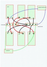
new battery config 2021.jpg
 
What you show will work fine. However, keep the wires from the batteries to the bus bar all the same length and take extra care to do good crimps on all the lugs. (One bad crimp will mess up the balance)

Also, Be sure to use extra heavy duty bus bars.
 
suggestions on the cable size required? they will each be about 3' long and the max draw on the batteries is from a xantrex 3000 w mod sine wave inverter.
also recommend on the bus bar? my amazon search didn't turn up much that looked like heavy duty bus bars.
What you show will work fine. However, keep the wires from the batteries to the bus bar all the same length and take extra care to do good crimps on all the lugs. (One bad crimp will mess up the balance)

Also, Be sure to use extra heavy duty bus bars.
 
Blue Sea busbars are highly regarded. Nice tinned copper with big lug posts.
bluesea.com
Some marine supply sites sell them as well.
 
suggestions on the cable size required? they will each be about 3' long and the max draw on the batteries is from a xantrex 3000 w mod sine wave inverter.
Total amperage for the inverter is 3000W/12V=250A.
The amperage per battery is 250A/6batteries = 42A/battery.
Looking at the Blue Seas ampacity chart, it calls for 6 AWG, but I would go with 4 AWG.
 
Blue Sea busbars are highly regarded. Nice tinned copper with big lug posts.
bluesea.com
Some marine supply sites sell them as well.

Blue Seas does make some good ones, but be sure you get one of their High amperage ones. Your total amperage is 250A. In order to avoid voltage drops, I would look for one that is rated no less than 300A..... More would be better.

Backing up a bit:
If the resistance from the inverter or charger to one battery is different than the resistance to another battery, then voltage drop to the two batteries will be different. That means the battery with the lower resistance path will be worked harder than the other one.

To avoid this, it is important to have the same resistance to each battery. That is why making the wires from the bus-bar to the battery as identical as possible is important. Since the bus-bar is in the current path, it is part of the resistance calculation as well. To minimize the impact of the busbar, you want it to be as low resistance as possible.... and that means you want the highest current rating possible.


You could make your own busbars. For this I would use 1/4" x 1 copper bar. (Onlinemetals.com is a good source)

This is a good link for finding the ampacity of copper bar.
https://www.copper.org/applications/electrical/busbar/busbar_ampacities.html

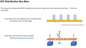
This resource has instructions on building distribution bus bars:

 
BTW: The drawing shows 4-post busbars with 2 lugs on each. When you do that, make sure the top of the bottom lug is flat. You need a solid connection between the bottom face of the top lug and the top face of the bottom lug.

I have seen a few problems with stacking lugs.
  • The crimp portion of the bottom lug was so close to the hole that the top lug could not sit flat on the bottom lug.
  • I had a batch of lugs that had a raised lip around the outside edge of the top of the lug face. The lip made it impossible for the top lug to sit on the face of the bottom lug (I have only seen that once.....but now I watch for it if I have to stack lugs)
  • Warped lugs. I once saw an instalation where the face of the lug was bent and the bolt holding it down was not tight enough to platen it out.
    I have no idea how it got bent. I assume it was not manufactured that way..... but some of the stuff that gets sold on-line can be pretty crappy.
The other thing to do is lightly sand or steel wool the faces of the lugs before you assemble them. This removes any oxidation or other contaminant that might be present.

Note: I would never stack more than 2 high current lugs.
 
If you get 8 batteries instead of 6, there are ways to use cables to connect pairs, and pairs of pairs, so they are perfectly balanced.

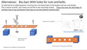
Stacking lugs on busbars: If you get a bare busbar with holes, you can "stack" but putting on ring terminal on the top, one on the bottom, and a bolt through. That way there is no stacking at all.

You've put inverter at one end of busbar. All current has to flow through cross section.
If you put inverter at middle of busbar, with half the batteries toward one end and half toward the other, busbar has max 1/2 of total current at any point.

My setup has a similar situation - one 48V string of batteries and four inverters. Busbar has 3 holes in use. Battery goes to center hole. Two inverters are wired top & bottom to left hole, two to right hole.
 
Stacking lugs on busbars: If you get a bare busbar with holes, you can "stack" but putting on ring terminal on the top, one on the bottom, and a bolt through. That way there is no stacking at all.

That is a good idea.... Most commercial bus bars are not like that but if you make your own it would be easy. The only thing is figuring a good way to mount it so you have access to both sides.... but that should be easy if you plan ahead.
 
Drill a copper bar, and mount it on standoffs like this:


Here's my ground busbar (with two fuse holders for positive side mechanically bolted to it)

 
Drill a copper bar, and mount it on standoffs like this:

Yup..... Like I said.... it is easy if you plan ahead. You could even use a block of wood if you wanted to save a couple of bucks.

Those standoffs are 1" high. That might be a little low for easily getting to the lugs and nuts on the bottom... but it would work.

Mounting it vertically might also be a good option for some situations.

1611701575766.png

I have a resource out there about building your own bus-bars. I think I will add these ideas to it. Thanks


That shows "soldered in" "all-thread" brass posts.
I would tap the holes they go in. Then sweat-solder (if not braze on one end)
Wouldn't want deep 60 degree threads filled with solder inside a smooth wall hole. If in the current carrying path that would put current through a considerable thickness of solder (but I believe the path is just lug compressed against busbar.) Also, not all that strong.
60/40 solder is 535 kgf/cm^2, 7600 psi. That's 1/4 of mild steel. Would prefer something that isn't going to get pulled out when tightening. With 1/4 square inch surface of that cylinder, 2000 lbs ultimate strength (assuming shear = tensile.)

http://alasir.com/reference/solder_alloys/

Or, consider flat-head screws like this, countersunk:


Either brass or stainless would work. The stud isn't the current carrying path, just mechanical, so cone shaped head takes the force.
 
Last edited:
That shows "soldered in" "all-thread" brass posts.
I would tap the holes they go in. Then sweat-solder (if not braze on one end)
That is exactly what the instructions say in the resource:

1) Print template (See printing instructions on template)
2) Cut ¼” x ¾” stock to length
3) Clean up cut edges with file and/or sandpaper.
4) Tape template to blank
5) Center punch all hole locations.
6) Drill holes ( 1/8 Mounting holes and 17/64 Post holes)
7) Clean up any burs on top or bottom of holes with file and/or sandpaper.
8) Tap post holes (See next page for detailed tapping instructions)
9) Cut all thread to 1” lengths. (Use dressing tool on each end)
10) Thread posts into bar. The post should be slightly less than all the way through bar.
11) With bus bar in vice with posts down, use propane torch to solder all thread into place from back of busbar.
The solder should go into the threads but should not come through other side. (If it does come through, flip
bus bar over (posts up), apply the torch to melt the solder, then wipe excess solder off with damp rag. BE
CAREFUL NOT TO BURN YOURSELF)
12) If the solder is lumped up on bottom of busbar, file it flat so the busbar will sit flat on mounting board.
Instructions
 
The soldering is to lock the studs in place, not to improve the conductivity. I have never had stud start to un-thread after I soldered them.

I tried the countersunk flathead screws and it worked OK.... However, once I counter sunk them deep enough that the heads did not protrude, there were only a couple of threads left in the copper. They still worked ok... till they started to loosen up. Since the bus bars were screwed down flat, the flat-head screws could not back out much. They still worked ok but it bothered me that they were loose. It did not happen but Without the head tight against the copper I was worried I could strip the couple of threads that were left. That is why I went to soldering the all-thread into threaded holes.

Would have to be thicker.
Threaded for the rod should be good enough.

If cheap high volume manufacturing, deform with a punch so it doesn't unthread instead of soldering.

I was looking for the male stud version of these:


I've see them (or at least tall female threaded pieces) installed flush in sheetmetal. Given 1/4" thick stock, a small head would retain it and spline would keep it from turning, but it would require a countersunk hole.
 
Back
Top