


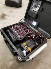
Built this battery box with a friends help, I think he exaggerated his knowledge a little and we ended up with this setup. I am aware of some issues that need to be fixed when I go through and re-wire it all, but if you see anything I missed feel free to chime in.
The major issue I am looking for an answer on, is these Li-Po pouch cells each have their own onboard BMS. On the first initial use, the voltage was brought too low and some of the cells shut down and now will not accept a charge, and when I plug in the BMS it just shows low voltage on two of them.
Can I just switch the charger to a Ni-MH charge setting and force charge them the way its hooked up, until the voltage gets high enough to be recognized then switch to Li-Po charging? Or do I need to charge the cells individually?
Current issues I noticed:
The setup needs to be a 3S configuration, currently wired as a 4S. The power inverter only accepts up to 15 volts for the top end, so most of the 352AH is unusable in the current 4S configuration
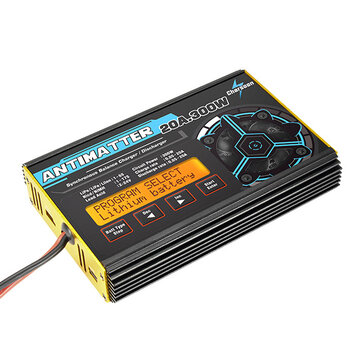
Needs a beefier charger. Took several days to fully charge.
I need a better BMS (I think)
Thanks,
Ryan
The major issue I am looking for an answer on, is these Li-Po pouch cells each have their own onboard BMS. On the first initial use, the voltage was brought too low and some of the cells shut down and now will not accept a charge, and when I plug in the BMS it just shows low voltage on two of them.
Can I just switch the charger to a Ni-MH charge setting and force charge them the way its hooked up, until the voltage gets high enough to be recognized then switch to Li-Po charging? Or do I need to charge the cells individually?
Current issues I noticed:
The setup needs to be a 3S configuration, currently wired as a 4S. The power inverter only accepts up to 15 volts for the top end, so most of the 352AH is unusable in the current 4S configuration
Needs a beefier charger. Took several days to fully charge.
I need a better BMS (I think)
Thanks,
Ryan


")


