diy solar

diy solar

High current BMS 300A plus

Is anyone using the new Chargery DCC contactor boxes? They call them bi-directional contactors since they replace their previous solenoid mechanical contactors but they look like MOSFET switches from specs. I don't like how close together they but the connectors but they look reasonably priced. Are they in-fact MOSFET's switches ?

Ignore the continous current claim and pay attention to the Series Resistance I added based on their claimed 100A voltage drop.
That kind of spec would be unusual for a mechanical contactor.
The 100v max voltage concerns me they are in fact MOSFET's as 100v breakdown MOSFET's would be mostly an unnecessary extra cost although it might make sense so they don't have to carry so many models for different voltage battery systems.
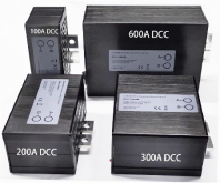
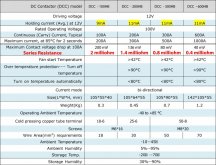
1607632579423.pngChargery DC contactor manual V1.0.jpg
 
I have a 300A DCC and it is a MOSFET design. I have not looked at it closely but it never even got warm with an 80A load. In fact, it has a thermal controlled fan that was never activated. The series resistance is probably fairly accurate.

For bi-directional control - the MOSFETs are in a back-to-back configuration with dual gate drivers (sometimes in a single controller IC). That allows it to block or conduct in both directions.

Of course it is silent, no 'ker-plunk' from a typical contactor.
 
What is the DCR of a decent contactor?
If I assume DCR = DC Rating then one Kilovac has a 500 Amp rating and draws 2 Watts. I understand the use case fort FET based control and I rely on them in some 12 V packs I built for relatives. Years ago I actually did weld the contacts on one with a human error that created multiple on off cycles, which were enough to defeat the precharge circuit on a motor controller.

I have at least 3 Kilovac contactors in my parts box so I am going to put them to good use in my bigger pack until they no longer work. Thanks for your information on FETS. I continue to learn.
DCR = Direct Current Resistance

The resistance of a switch (any switch) will determine the amount of heat generated per amp of current flowing through.

A contactor has a coil that needs a certain amount of power to keep activated - usually some number of watts which is not trivial. The contacts on the contactor have some resistance like any other switch. The resistance creates a voltage drop that is proportional to the current passing through. That resistance is usually so small that you cannot measure it with a conventional handheld meter - but when the amps start flowing the heat will build. At 300A a contact with .001 (which is very low) ohms will be dissipating (wasting) 90 watts!.

In a MOSFET design, you can parallel a lot of them. Each additional FET will reduce the total resistance and therefore the amount of heat generated. The energy needed to control and activate a MOSFET is so tiny that special equipment is needed to measure it.
 
Just a pinch of extra info . During my tests, I have pushed 150A charge through a single 300A DCC for over 2 hours, never got warm, fan never kicked on. Pulled 160A for 30 Min and same thing, cool and no fan. I built things for 300 "theoretically Continuous" knowing I would never need to hit that. Over-building a bit adds a margin I prefer, especially living in the middle of nowhere. Just like having spare critical backup components. BTDT, Lessons Learned.
 
Just a pinch of extra info . During my tests, I have pushed 150A charge through a single 300A DCC for over 2 hours, never got warm, fan never kicked on. Pulled 160A for 30 Min and same thing, cool and no fan. I built things for 300 "theoretically Continuous" knowing I would never need to hit that. Over-building a bit adds a margin I prefer, especially living in the middle of nowhere. Just like having spare critical backup components. BTDT, Lessons Learned.
Pretty much any mechanical contactor would be rather warm with 150A.

Seems like an efficient design.
 
Actually, if you go back to the old SSR testing threads and related, you'll see a few electro-mech's got shall we say "tested" and heat... wow.... Result, Big Push for SSR tech and voila.... ;)

SHNOOTZ, Way off-topic, sorry, back to regular programming.
 
Well not ALL contactor are equal either.
You have the standard ones, some of which can be Real Power Hogs.
You have Every Savers which are considerably more energy efficient.
Then you cross into Solids State territory, even more energy efficient but also with some tradeoffs depending on type and quality of components within.

TE Connectivity Kilovac EV200AAANA Contactor 500A 12~24VDC contactors
SPECS DOC LINK: https://www.te.com/commerce/Documen...200_Ser_Contactors&DocType=CS&DocLang=English

Dongya DH (Unidirectional) & DHV series (Bi-Directional)
High Voltage DC Contactor,High Voltage Contactor,DHV dc contactor - China Dongya Electronic (cndongya.com)
* You have to request DVH Bi-Directional.
DATASHEET PDF: https://diysolarforum.com/attachments/dhv200-engery-saving-datasheet-2233-pdf.13061/

These Biig SSR's came out as a result of Craig & I's Relay, Contactor SSR testing a while back. At that time no one had Large Lugs SSRS to actually handle real battery cables. These guys took on the challenge and created this Shown below is the 500A versions I received. After these were made up, and Jason from Chargery had communicated with that Company, he realized it would be prudent to develop the DCC inhouse which is how they came to be in existence. NB: These are Unidirectional Versions suitable ONLY for Split Port config. Bi-Directionals are available but +$$$ and are special order, which would have to goto Manufacturing to be made on req. Both of these versions were made up specifically at my request and my additional expenses. They are now available for everyone

The Real Deal 500A (1/2" Lugs)
500a-ssr-face-jpg.12566


500a-ssr-profile-jpg.12567


IF you are Curious:
Big Lug 500A SSR : https://www.alibaba.com/product-detail/DC-control-DC-solid-state-relay_62549649837.html?spm=a2747.manage.0.0.3d1571d2AmThhr&bypass=true

Big Lug 1000A SSR : https://www.alibaba.com/product-detail/DC-control-DC-solid-state-relay_62549285366.html?spm=a2700.icbuShop.41413.11.72317242imd258&fullFirstScreen=true&bypass=true
Dare i ask, if these SSR are so efficient, why the big arse heatsink?
When the spec sheet rounds the max on state voltage drop up to 1v, it doesn't inspire much confidence when they cant even rate it to hundreds of milivolts. p=IV. Even at 500 amps, thats potentially a nice 500W heater you have there. Theres a reason why high current SSRs have or require large heatsinks. and EVs use contactors/relays
 
A quality MOSFET array will use milliwatts for operation (if that). Common NFETS can do enormous currents at sub mOhm ranges.
A parallel 1mOhm NFET 8x array would be around 125uOhms. This is about 11 watts at 300 Amps over 8x devices. Not a huge thermal challenge.

What is the DCR of a decent contactor? Are they really able to beat that? I have no practical experience with mechanical contactors - only variants of MOSFETs Si, Sic, GaN. Hard to imagine a physical device beating them but I could be wrong.
The heat from a mosfet comes from the voltage drop across them, not from the milliwatts required to operate them.
 
So are you saying that the voltage drop does not count as Watts to operate?
well technically if there was no current but the thing was still turned on, there would be no voltage drop and no energy loss on the switching device.

Yes a SSR will win out strictly in energy required to operate any day of the week.
But when it comes to energy lost in operation, the tables start turning when you increase the current flow. you can increase the capacity of a SSR by effectively just building more in series, but that voltage drop is always fixed, based on the silicone tech used to build it.

I like to think of it as energy required to operate vs energy lost in the switch, and 2 different lots of arguments for and against the different techs.
SSRs consume less energy in operation alone, before you start passing current. Mechanical contactors/relays consume more energy to operate.
At lower currents SSRs lose less energy due to voltage drop accross the load terminals, at higher currents the the tables start turning.
 
Last edited:
Dare i ask, if these SSR are so efficient, why the big arse heatsink?
When the spec sheet rounds the max on state voltage drop up to 1v, it doesn't inspire much confidence when they cant even rate it to hundreds of milivolts. p=IV. Even at 500 amps, thats potentially a nice 500W heater you have there. Theres a reason why high current SSRs have or require large heatsinks. and EVs use contactors/relays
Efficient does not mean perfect.
Contactors are used in fail-safe situations to compliment a MOSFET switch. I physical disconnect is the ultimate way to disconnect a load, but a terrible way to make and break huge currents. In an emergency, who cares but in a typical application the load is removed before a contactor is disengaged to get decent life out of it. MOSFETs can switch hundreds of amps almost until the end of time. Think of the VFD in an electric car - hundreds of volts being switched tens of thousands of times per second over many years.

MOSFETs are really really good at their job - switching.


Chargery claims 80mV drop at 100A which is about 800uOhms (.8 milliOhms) and 8 watts. So, maybe 25 or so watts at full load which is rather amazing. That needs some heat sinks because all of that heat is being generated in a very small area, the dies of the MOSFET.

A contactor is conducting the current over a very large layered surface to get the resistance as low as possible. They get hot, but not as sensitive to heat and the mechanical contruction with copper plates are natural heat sinks.
 
The heat from a mosfet comes from the voltage drop across them, not from the milliwatts required to operate them.
Which I explained in the example calculating 11 watts from the voltage drop at 300A. Pretty amazing for a total footprint of 8 tiny MOSFETs.
 
Efficient does not mean perfect.
Contactors are used in fail-safe situations to compliment a MOSFET switch. I physical disconnect is the ultimate way to disconnect a load, but a terrible way to make and break huge currents. In an emergency, who cares but in a typical application the load is removed before a contactor is disengaged to get decent life out of it. MOSFETs can switch hundreds of amps almost until the end of time. Think of the VFD in an electric car - hundreds of volts being switched tens of thousands of times per second over many years.

MOSFETs are really really good at their job - switching.


Chargery claims 80mV drop at 100A which is about 800uOhms (.8 milliOhms) and 8 watts. So, maybe 25 or so watts at full load which is rather amazing. That needs some heat sinks because all of that heat is being generated in a very small area, the dies of the MOSFET.

A contactor is conducting the current over a very large layered surface to get the resistance as low as possible. They get hot, but not as sensitive to heat and the mechanical contruction with copper plates are natural heat sinks.
how often does a BMS kick in to disconnect the load though? It is soley there to protect your battery. if your system is designed and sized appropriately it should be always on.

80mv is pretty good if it does live up to that, much better than what most offer of 1v

But yes, back to OP
Pick whater BMS you like the features of, and get a relay/contactor/SSR to do the switching work
 
well technically if there was no current but the thing was still turned on, there would be no voltage drop and no energy loss on the switching device.

Yes a SSR will win out strictly in energy required to operate any day of the week.
But when it comes to energy lost in operation, the tables start turning when you increase the current flow. you can increase the capacity of a SSR by effectively just building more in series, but that voltage drop is always fixed, based on the silicone tech used to build it.

I like to think of it as energy required to operate vs energy lost in the switch, and 2 different lots of arguments for and against the different techs.
SSRs consume less energy in operation alone, before you start passing current. Mechanical contactors/relays consume more energy to operate.
At lower currents SSRs lose less energy due to voltage drop accross the load terminals, at higher currents the the tables start turning.
No.

The effective resistance of a MOSFET based SSR is not fixed in any way. They are arranged in parallel and each addition reduces the resistance. You fairly quickly get the point where the MOSFETs are a lower resistance than the connections themselves.

Take an Infineon OptiMOS device that is 750uOhms RdsOn - put lets say 8 in parallel. You get a total device resistance of 95 microOhms.
At 300 amps that is a paltry 8.5 watts which a small passive heat spreader would easily deal with.

SSRs win in most categories - efficiency, cost, and reliability. When a physical air-gap is required for disconnect - mechanical contactors are the only option.
 
how often does a BMS kick in to disconnect the load though? It is soley there to protect your battery. if your system is designed and sized appropriately it should be always on.

80mv is pretty good if it does live up to that, much better than what most offer of 1v

But yes, back to OP
Pick whater BMS you like the features of, and get a relay/contactor/SSR to do the switching work

Hopefully the contactor is never used to switch a load - which is why this method has been popular in this application. The contactors are the disconnect of last resort. Still, they get hot because they use a lot of power on a good day. Contacts get dirty, coils go bad, things get sticky on a bad day.

Me personally, I pretty much only want a MOSFET disconnect and a physical fuse for the last resort.
 
Chargery claims 80mV drop at 100A which is about 800uOhms (.8 milliOhms) and 8 watts. So, maybe 25 or so watts at full load which is rather amazing.

It'll be more like 72 W @ 300 A (P = R * I²) and that's why they need a fan... not the worst FETs but not the best ones either.
 
It'll be more like 72 W @ 300 A (P = R * I²) and that's why they need a fan... not the worst FETs but not the best ones either.
Lol, you are totally right. I stand corrected. Should be a lesson in rapid-fire posting :LOL:

There is a balance between using the expensive ultra-low-restance FETS and using the lower-cost parts but needing 3x more of them to get the needed RdsOn.

The more FETs you have the lower the requirements for thermal control become. Get great parts or add additional FETS and you may get to lose the fan, all the cutting, hardware, and electronics that go along with it. I really dislike fans in places that are critical and un-monitored like battery banks.

It happens to me too, no worries ?

Yep, easy and cheap is cheap FETs + fan, harder and more expensive is low Rdson FETs + passive heatsink.

I don't like fans either on something that should not need any maintenance and/or is running 24/7...
 
Last edited:
It happens to me too, no worries ?

Yep, easy and cheap is cheap FETs + fan, harder and more expensive is low Rdson FETs + passive heatsink.

I don't like fans either on something that should not need any maintenance and/or is running 24/7...
it might work for me... 98% I would be under 50 A
 
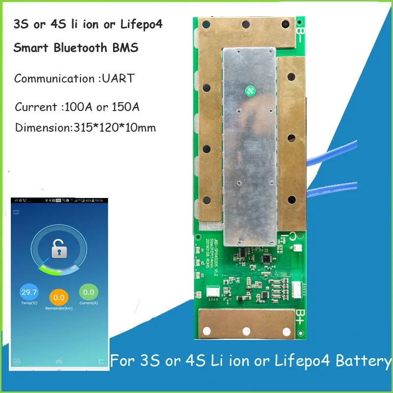
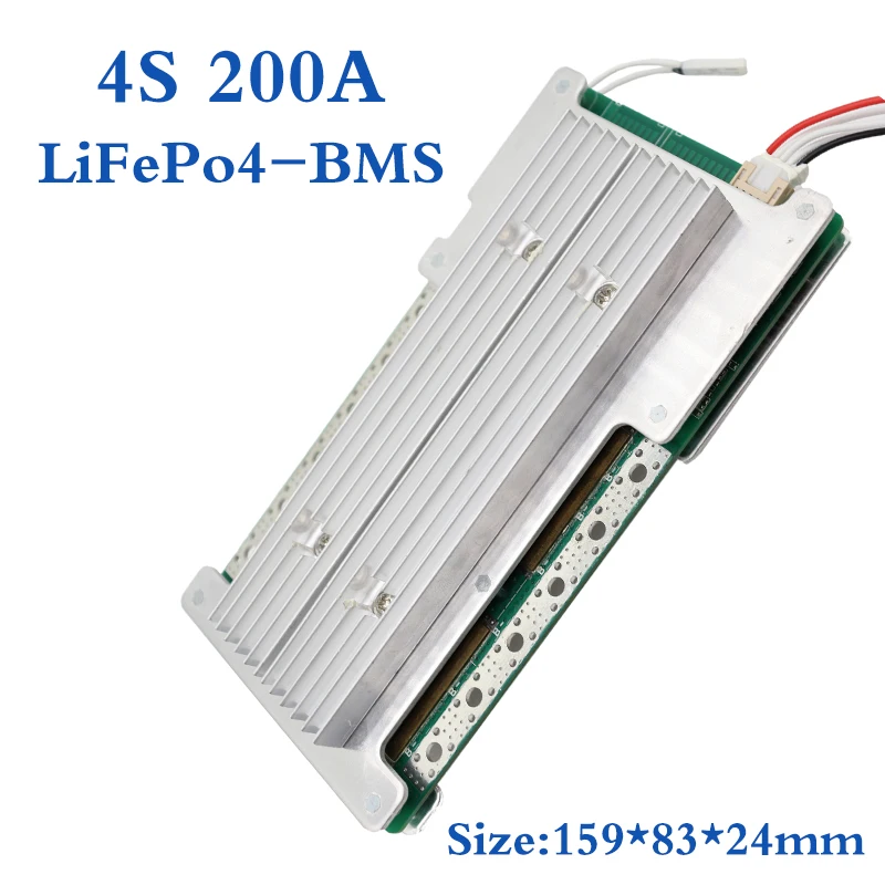
I’d be interested if it was possible to add heat sinks to one of the jbd style FET BMS units to achieve more sustained top end current thus reducing risk of blowing the BMS. I guess heat sinks could be added to the FETs and also adding a copper bus bar and thick heat draining lugs with 70mm2 cable .

I’m planing on beefing up the below unit rather than dropping addition money on a


I’d be interested if this has been attempted . There seems to be ALI sellers adding aftermarket heat sinks and boosting the current adverted

Here is an example

 
Last edited:
I wonder why they do not provide the Balancing current on the one with the adeed HS.. I also wonder how big of the wire gauge can fit into those solder holes.
 

diy solar

diy solar
Back
Top