diy solar

diy solar

High Frequency Inverter battery current waveform

Hedges

I See Electromagnetic Fields!
Joined
Mar 28, 2020
Messages
21,831
In the interest of science ;) I have captured waveforms drawn by a high frequency inverter from the battery.
This could give some insight to how a BMS might react.

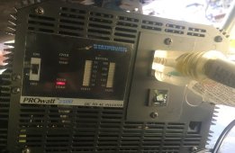
About 25 years ago I found myself with idle hands and some money ($800?) burning a hole in my pocket. I wandered into Quement Electronics in San Jose and walked out with a StatPower PROwatt 2500W inverter (12V battery to 120VAC modified square wave.)
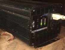
StatPower PROwatt IMG_2343.jpg

The guts include a bank of transistors and transformers
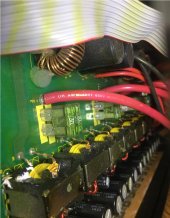
Guts of Inverter IMG_2340.jpg

Instrumented with a DENT current transformer (333 mV/100A) on AC output,
Fluke i2000FLEX 200A, 2000A Rogowski Coil on battery cable (10 Hz to 20 kHz response)
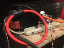
Current Probes IMG_2345.jpg

SunXtender 104Ah 12V AGM battery (14 years old, about 40% capacity remaining)
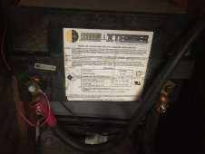
Battery IMG_2346.jpg

Test Results

Battery Amps (per Ames clamp)VDC nominalW(DC)AC Irms (per Fluke i2000)VWEfficiency
Off
0.5​
12.7​
6.35​
0.03​
120​
3.6​
57%
Low
64​
11.5​
736​
5.44​
120​
652.8​
89%​
Medium
77​
11.4​
873.95​
6.44​
120​
772.8​
88%​
High
124​
10.8​
1333​
10.67​
120​
1280.4​
96%​
120​
"C" rate
3.0​
discharge on high, vs. remaining battery capacity

The efficiency figure for no-load is bogus, reflects a 30 mA AC draw that is probably zero-offset error in the scope.
At the "high" setting of DeLongi radiator heater, it was giving low-battery alarm. Might not have done that with a new battery, but this one is in poor shape.

TDS 784DTek scope
P5210ATek high voltage probe
i2000FLEXFluke 200/2000A probe (Rogowski Coil)
CT-S-SC-0100DENT 100A current transformer (with resistor, 333mV = 100A)
77IIIFluke DMM
CM1000AAmes (Harbor Freight) clamp DC ammeter (Hall effect)

The waveforms are where it gets interesting.

With heater switched off, inverter sucks a 15.6A gulp of current from battery once every 7 cycles. Clamp ammeter reported 0.5Arms (which isn't the correct average to compute power from DC battery; need mean)

The Modified Square Wave AC output has a dead-time at zero volts and plateau of +/-145V. DMM reads 120 Vrms.
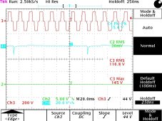
PROwatt noload 053022 1017.jpg

With heater on "low", AC current resembles AC waveform, and is 5.44Arms.
Battery current is 54.7App ripple on scope, 64Arms on clamp meter.
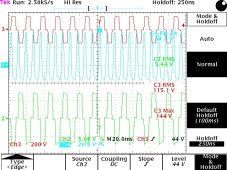
PROwatt heater low 053022 1017.jpg

Heater on "medium", AC current is 6.44 Arms.
Battery current waveform is 22.1 App, riding on 77 Arms per clamp.
Scope reading of current appears lower for "medium" than for "low" because switching power supply is now in "continuous conduction mode", a sawtooth waveform that doesn't drop all the way to zero. Because probe is AC not DC, scope doesn't reflect the offset that clamp ammeter shows.
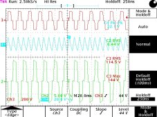
PROwatt heater medium 053022 1017.jpg

Heater on high, AC current 10.67A
Battery current 40.2 App riding on 124Arms.
That's about 164A high, 84A low.
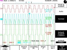
PROwatt heater high 053022 1017.jpg


The instantaneous peak battery current of 164A is 1/3 higher than the 124A RMS average current reported by clamp ammeter. This was powering 1300W load with a high-frequency inverter that has pretty good set of electrolytic capacitors.
Would expect similar current for a 48V battery inverter powering 5200W.
But this was with a worn-out AGM battery being discharged at 3C relative to its remaining capacity.
If a fresh lithium battery, would expect voltage to hold up better so more ripple current from battery.
 
You are a legend Hedges - but you definitely have way too much time on your hands! Love your input though, very interesting.
 
Nice work ;)

It would be interesting to see an MPP Solar, Growatt or other good AIO inverter's diagram.
One with higher (450-500Voc) MPPT.
They have an isolated two way buck/boost converter on the battery side.
And that feeds the 400V DC BUS (and 500V capacitors there) where the inverter takes the power to make AC.
 
(If I disappear into the garage, I get to tinker instead of having to do yard chores.)

I previously measured battery current waveform of Sunny Island, found that most of 60 Hz ripple current comes direct from battery.
Maybe some AIO are DC coupled on the battery side, but SolArk (and the names you list?) couple PV into the HV rail.

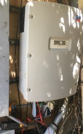
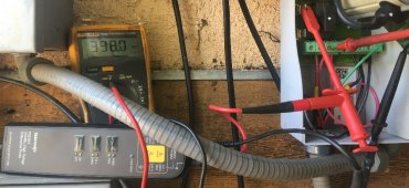
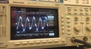
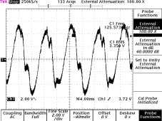
I measured PV input to transformer-type GT PV inverter Sunny Boy 5000US. 250V to 600V PV, so transformer likely has 1.36x ratio, able to deliver 340Vpeak on secondary from 250V input buck converter. Has no batteries, so capacitors have to supply the ripple current.
398 VDC from PV, 3.35 Vrms ripple on the capacitors to supply AC current. 4kW at 240Vrms, 16.7Arms

SB 5000US IMG_2301.jpg Voltage probe IMG_2296.jpg scope ripple IMG_2302.jpg

SMA 5000US PV ripple 052122.jpg
 
I know what you mean "disappear into the garage" ?

The PV side is not isolated. Not in any PV system I ever saw.
It would "ruin" the 95-96-97... % conversion rate(war)s from PV to AC.

But in better systems the Battery side is isolated.

That reminds me ... One user from the Hungarian group made this video (sorry it is in hungarian and YT no longer allows other users to make subtitles)
But a picture is worth 1000 words ... and a video is worth 1000 pictures :)

So what you see is a simple test.
  • simple 12V battery
  • connected to a "simple" inverter that gives out 200-230Vac.
  • 230Vac connected to RCD.
  • 2 (simple) ground rods
  • and forced grounding
Inverter gives out a floating ground.
Connecting one port to the left ground rod ... and it is grounded.
Now RCD breaks if over 30mA imbalance.
(this is how you should connect your inverter into a TN-S, TN-C-S system)

But ... the inverter is not isolated.
On the battery terminals there is 110-110Vac to ground.
And not only Volt, but current too.
He measured 0,7A on both terminals to the remote ground (inverter gives out only 2 - 2,2 A).
To the connected ground ... inverter shut down with SC.

That can be lethal if you touch the battery terminal.
You see the irony ... how touching a perfectly safe 12Vdc battery terminal can kill you :)


Last edited:
For these older inverters, PV is transformer isolated from AC, and they achieve 94% to 97% efficiency. Transformerless a bit higher.


This model can be either positive or negative ground (through 1A ground-fault fuse). This particular one I've negative grounded due to which type of PV panel.

I figured non-isolated battery inverters would drive battery to high AC voltage if AC was grounded. Of course some HF types are isolated.
 
For these older inverters, PV is transformer isolated from AC, and they achieve 94% to 97% efficiency. Transformerless a bit higher.


This model can be either positive or negative ground (through 1A ground-fault fuse). This particular one I've negative grounded due to which type of PV panel.
I can not imagine how they can achieve 97% efficiency with an LF inverter.
That is a lot of wire, a lot of copper. That has resistance, and the loss from the magnetic field and heat ...
A simple transformer has 95-98% efficiency.
And that does not have the Buck converter and an inverter before it :)


I figured non-isolated battery inverters would drive battery to high AC voltage if AC was grounded. Of course some HF types are isolated.
And if you think about it, many "hybridized" inverters (Fronius GEN24, Huawei Sun2000 M1) have the DC BUS directly connected to a high V battery.
Without an isolating buck/boost converter.
And the inverters are force grounded ...
 
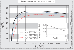
At 3000W load of 7000W inverter, with 250V PV input. (Transformer turns ratio is probably ~ 340/250, so buck converter delivers 1:1 at peak of sine wave.
A lot of copper, and < 1/4 of full-load losses.

These were designed back when PV panels were expensive.
Then SMA figured out how to get utility to accept transformerless. Can you imagine what would happen if PV DCV was applied to utility transformer?!

1654044211896.png

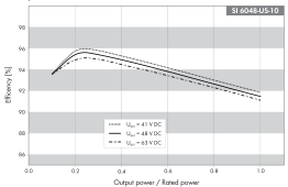
96% at 1500W from 6kW battery inverter, if 41V battery. Turns ratio = 170/41?

1654044411249.png
 
Nice work ;)

It would be interesting to see an MPP Solar, Growatt or other good AIO inverter's diagram.
One with higher (450-500Voc) MPPT.
They have an isolated two way buck/boost converter on the battery side.
And that feeds the 400V DC BUS (and 500V capacitors there) where the inverter takes the power to make AC.
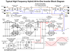
All the HF hybrid inverters use the same basic configuration. 120vac models run at lower HV DC than 240vac models. The PV SCC is boost only, up to the inverter internal HV DC supply. It sets the maximum allowed PV input voltage as the PV boost converter is not allowed to exceed internal HV DC supply. If you notice, 120vac models have a lower maximum PV input voltage limit. The PV inputs are also not isolated from AC output so PV is riding on AC polarity chopping when neutral is grounded.

Battery side is really two different circuit functions that reuses parts of the circuit. It is a boost only for inverter HV supply and switches modes to buck conversion for battery charging. They have an extra IGBT or MOSFET and rectifier diode for the charger buck operation. It cannot instantly change from forward boost to reverse buck like a low freq inverter can. It takes a little time to switch between boost to buck modes. This is why the Chinese HF inverters cannot do load shaving with AC input. They only allow battery charging and AC pass through when AC input is present. They cannot switch from buck converting for charging battery and boost converting to run inverter fast enough to do load shaving of AC input power. Since PV power goes to internal HV DC it is under the same battery to HV DC converter mode restrictions.

It takes a true bi-directional battery DC to HV DC converter to do load shaving. This is a much more difficult design. SolArk inverters are close to true bi-directional because they have much more HV DC filter capacitor storage to ride across the converter flow direction change.

A low freq inverter can reverse power flow on the fly, instantly. They don't even need immediate controller intervention to change the PWM cycling. PWM adjustment is done a bit after the reversal to refine the voltage regulation.

HF inverter block diagram.png
 
Last edited:
All the HF hybrid inverters use the same basic configuration. 120vac models run at lower HV DC than 240vac models. The PV SCC is boost only, up to the inverter internal HV DC supply. It sets the maximum allowed PV input voltage as the PV boost converter is not allowed to exceed internal HV DC supply. If you notice, 120vac models have a lower maximum PV input voltage limit. The PV inputs are also not isolated from AC output so PV is riding on AC polarity chopping when neutral is grounded.
Not sure about that :)
The new LVX6048WP has 600Voc MPPT.
So I think it is also a 400V DC Bus model.
And in this case the MPPT needs to be a buck/boost type ... or the DC BUS needs to be raised from max 500V to 600V ;)


Battery side is really two different circuit functions that reuses parts of the circuit. It is a boost only for inverter HV supply and switches modes to buck conversion for battery charging. They have an extra IGBT or MOSFET and rectifier diode for the charger buck operation. It cannot instantly change from forward boost to reverse buck like a low freq inverter can. It takes a little time to switch between boost to buck modes. This is why the Chinese HF inverters cannot do load shaving with AC input. They only allow battery charging and AC pass through when AC input is present. They cannot switch from buck converting for charging battery and boost converting to run inverter fast enough to do load shaving of AC input power. Since PV power goes to internal HV DC it is under the same battery to HV DC converter mode restrictions.
I am not sure about this part.
All new MPP Solar inverters can do load shaving (GK, MKX, MGX, MAX, LV6548, ... ).
So 5kW load comes from 3kW PV and 2kW utility (mixed together) ... even without battery.
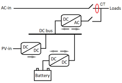
Your scheme is perfect, maybe a bit too much :) (but perfectly shows the isolated two way battery-DC Bus buck/boost converter what I like)

This simplified scheme is enough to most users to understand the inverters inner working (not the double conversion MKX, that is different)

MPP_Solar_MGX_schema_limiter.png


It takes a true bi-directional battery DC to HV DC converter to do load shaving. This is a much more difficult design. SolArk inverters are close to true bi-directional because they have much more HV DC filter capacitor storage to ride across the converter flow direction change.

Load shaving from battery?
I never tried. I think the FW is not up to it.
I think it could do direct load shaving from battery, but maybe not battery + PV.
So good question ... since it can give power to the load from PV+battery combined I do not think it would be impossible for them to implement.


Sol-ark inverters can do AC Coupling.
So they need to generate the sine wave (from battery) to the AC line and store excess production from this AC line (that the grid-tie put in top of there sine wave) into the battery ... at (almost) the same time :)
That is a bit more complex :)
But the new MPP Solar LVX6048WP can do it too.


A low freq inverter can reverse power flow on the fly, instantly. They don't even need immediate controller intervention to change the PWM cycling. PWM adjustment is done a bit after the reversal to refine the voltage regulation.

View attachment 96686
 
Is there anyway to cheaply cleanup those AC output waveforms. I have an inverter that causes the lights to blink under light loads. thanks.
 
Not sure about that :)
The new LVX6048WP has 600Voc MPPT.
So I think it is also a 400V DC Bus model.
And in this case the MPPT needs to be a buck/boost type ... or the DC BUS needs to be raised from max 500V to 600V ;)
You mean this LVX6048 low freq inverter? It does not have an inverter HV DC bus.

LVX6048 LF MPP inverter copy.png

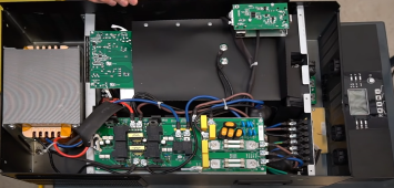
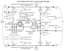
I don't know the SCC for LVX6048 but choices for all-in-one LF inverters are do a buck to battery DC coupling or make a parallel GT inverter to feed AC coupling into AC output of LF inverter since there is no HV DC point in LF inverters battery to AC output.
LF hybrid inverter block diagram.png
I would prefer a GT inverter in parallel with direct hard-wire control by LF inverter controller. It is best of both worlds, as it does not add ripple current to battery and gives better efficiency converting from PV to AC output. The hard-wired all-in-one control of a parallel AC output GT inverter would eliminate the issues separate unit GT inverters have with hybrid inverters to control excess PV power.

The manual states that if LVX6048 inverter is in standby mode only the PV can charge battery. This implies the SCC is not a parallel GT inverter circuit and SCC outputs to battery node directly, like Growatt LF inverter does. A parallel GT-like inverter for SCC would require hybrid LF inverter to be active to allow PV GT parallel AC power to be converted for battery charging.

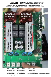
The Growatt LF inverter's SCC converts PV directly to battery node. It is buck only. PV to AC output goes through same path as battery using battery to main AC LF inverter. It has the loss of buck converter plus loss of AC LF inverter in PV to AC output power. Growatt LF inverter PV input is limited to 245v Vmp. With 430v max Vmp of LVX6048 they should not be using a simple inductor buck design like Growatt. Likely has HF transformer voltage down conversion to battery voltage or does a parallel GT AC output inverter. Hopefully the later.
12k MPPT SSC controller bd.png
.
 
Last edited:
You mean this LVX6048 low freq inverter? It does not have an inverter HV DC bus.

View attachment 96732

I don't know the SCC for LVX6048 but choices for all-in-one LF inverters are do a buck to battery DC coupling or make a parallel GT inverter to feed AC coupling into AC output of LF inverter since there is no HV DC point in LF inverters battery to AC output.
View attachment 96754
I would prefer a GT inverter in parallel with direct hard-wire control by LF inverter controller. It is best of both worlds, as it does not add ripple current to battery and gives better efficiency converting from PV to AC output. The hard-wired all-in-one control of a parallel AC output GT inverter would eliminate the issues separate unit GT inverters have with hybrid inverters to control excess PV power.

The Growatt LF inverter's SCC converts PV directly to battery node. It is buck only. PV to AC output goes through same path as battery using battery to main AC LF inverter. It has the loss of buck converter plus loss of AC LF inverter in PV to AC output power. Growatt LF inverter PV input is limited to 245v Vmp. With 430v max Vmp of LVX6048 they should not be using a simple inductor buck design like Growatt. Likely has HF transformer voltage down conversion to battery voltage or does a parallel GT AC output inverter. Hopefully the later.
View attachment 96738


You are right
I always forget that MPP makes LF inverters for US :)
For us in EU (and the whole world except US) they make only HF inverters.


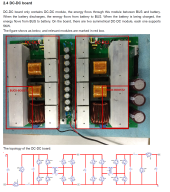
This is the MPP Solar MPI hybrid's battery module. It has two parallel 5kW two way, isolated buck/boost converter
It converts the 48Vdc to the DC BUS Voltage (I think it is 400Vdc in this 3 phase (3x230Vac) inverter too).


MPI_hybrid_10k.png


And here is the two MPPT (and the inverter on the right) that's are also connected to the same HighV DC Bus

MPI_hybrid_10k_MPPT_inverter.png


But in lower MPPT V units I saw what you mention.
Where there is a second LowV DC Bus too.
The MPPT is converting down to battery V ... and only from this lowV DC Bus is an isolated converter to the HighV DC Bus ... where the Inverter gets the power.
It is better ... and worst in the same time.
So the PV is isolated from AC ... and that is good.
More conversion loss from PV to AC ... and that is bad.
Also the PV is not isolated from battery, charging is raw ... and that is ugly.


So the Sol-ark is HF if I remember correctly (only saw the EU version Deye)
It can do AC coupling because it can faster switch the inverter to rectifier mode ?
 
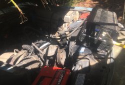
Planning to use the 2500W Statpower on my K2500 work truck, which has two 12V Odyssey batteries in parallel.
Here it is, temporarily connected at one battery+ and one block- (at least one battery connected by all copper, not cast iron.)
I want to either mount it behind the seat, or somewhere exterior shielded from rain and splashing.


StatPower K2500 IMG_3993.jpg

With 100' extension cord to an air compressor (12A 120V induction motor) it started and ran until tank full.
StatPower indicated 150A current draw.


1690731494409.png
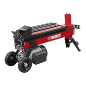
Armed with that confidence in inverter's performance, I purchased Harbor Freight electric log splitter


1690731601900.png


Motor just hummed for a moment, and I released the switch. Second try a little longer, inverter shut off with Overload fault.

StatPower overload IMG_3999.jpg

I was going to return the splitter, because I had wanted to use cordless chainsaw and this splitter at my wood lot.
But maybe I'll keep it, carry cut logs to my place, split and stack them to dry there instead.

Northern Tool does have a cordless splitter. 10x the price. I want to run off my truck's battery (which I plan to back up with lithium battery feeding 12V charger, and solar panels charging lithium.)


After switching off the inverter, I hopped back up on the truck, balanced myself with one hand on StatPower, other on block to disconnect cables.
I received a distinct AC shock in my hand!
No power cords to truck, inverter off ... but still making AC and chassis hot!
Checking with DMM, StatPower turned on has chassis 60Vrms relative to truck (negative battery cable). Turned off, it continues to make AC for a while, declining voltage. A pilot light on output would be useful as a warning, and to discharge HV capacitors faster.

I need to stop making a habit of this ...


diy solar

diy solar
Back
Top