SamValiant
New Member
- Joined
- May 14, 2020
- Messages
- 26
If you're on a boat you should probably think about having a galvanic isolator


lets walk through it.
They probably expect you to share the Ground on the output with ground on the input. What does the manual say?One minor point is that the output side of the AC does not have a ground terminal. The input has one and there is a screw on the steel chassis, but nothing on the terminal block that has the line and neutral output.
BTW: A lot of the ALL-IN-ONE units have Ground fault protection on the Solar input. In this case, the DC Negative is typically grounded through the Ground Fault circuit and should *NOT* be tied to ground elsewhere.The NEC requires any circuit operating above 50V to be grounded. A Nominal 48V system will run as high as 60V so the NEC requirement is that it must be grounded.
Ideally you would have all of the grounds for your DC equipment on one ground bus. The DC negative would also be tied to this bus. Meanwhile, all of your AC equipment ground are on a 2nd ground bus. A single wire between one of the two buses tie them together. Typically the AC ground bus would also be tied to earth ground....meaning the DC ground is tied to earth ground as well.
Note: I typically find the best way to tie the DC ground bus to the AC ground bus is to tie the ground lug of the inverter to the DC ground bus. Since the inverter ties AC ground to the lug, this ties the AC grounding to the DC grounding.
You may want to review this series of resources:

Grounding Made simpler - Part 1: AC/houshold grounding
To get the paper, click on the orange button at the top of the screen. The subject of grounding is a complex, multifaceted subject, that is often treated as an after-thought but needs to be considered from the beginning of the design and build...diysolarforum.com
diysolarforum.com
That's what I assumed, but the manual shows the output ground wire going to the screw on the chassis.They probably expect you to share the Ground on the output with ground on the input. What does the manual say?
Good info. I downloaded and scanned through the manual and did not see where it talks about N-G bonding....but your description makes sense for that style of inverter. I did notice that it said the Neutral in and out are tied together. I will try to get it added to the resource soon.SMA Sunny Island (SI-6048US, etc.)
Has two ground lugs for up to 4 awg, one AC input and one AC output. They are connected together and to chassis.
It has a larger (2/0 or so) lug for battery grounding connected to chassis. SMA says grounding the 48V battery is optional, and can be positive and negative.
NEC may want the battery grounded, but SMA doesn't care.
It has PTC fuses (0.5A) on both battery positive and negative, for use powering the two dry-contact SPDP relays it controls (or they can switch AC.
Neutral is not bonded to ground internally. Inverter is supposed to be hard wired, with neutral bonding outside.
This is not a surprise. The only time I have seen an inverter that cares is when they have built in SCC with Ground Fault detection.NEC may want the battery grounded, but SMA doesn't care.
The ground is all tied together so the only thing that matters is that the AC out ground is connected to one of the spots. They probably show it going to the chassis lug because the AC-in connection can't fit both ground wiresThat's what I assumed, but the manual shows the output ground wire going to the screw on the chassis.
Good info. I downloaded and scanned through the manual and did not see where it talks about N-G bonding....but your description makes sense for that style of inverter. I did notice that it said the Neutral in and out are tied together. I will try to get it added to the resource soon.
This is not a surprise. The only time I have seen an inverter that cares is when they have built in SCC with Ground Fault detection.
BTW: Do you have an SI-6048US? How do you like it? It looks like a nice unit and Sunnyboy is a well known brand.
++The model is PWRI150024S. I don't have a schematic, probably should have asked for one, but I found the explanation to be credible. If there is a ground short, there would be a difference in the current flow between line and neutral which would allow the inverter to sense it. The inverter does sense ground and will trip for that. I'm not ready to say it's a bed design. but I would think that the system should still have a chassis ground. Then again, I,m not a licensed electrician but I have stayed at a Holiday Inn before.Interesting. What model do you have? According to the manual for the LV2424 inverter/charger this is conceptually the way it should work:
View attachment 57346
(Unlike many companies, Aims documented the LV2424 grounding scheme pretty well.)
As you can see, When on battery, the LV2424 creates the N-G bond and when on shore power it does not. This is pretty standard for a good inverter/charger because you always want one and only one N-G Bond and shore power should always have a N-G Bond.
That seems like a really bad design for an inverter. It completely prevents one of the primary purpose of the 'ground' wire in the AC wiring from working: A short to the ground wire will not pop the breaker and clear the fault.
I just looked up the manual for this and it is striking how poorly documented it is compared to the Aims LV2424. I am pretty sure this is a rebrand of another companies inverter that is targeted at the lower price market.The model is PWRI150024S
The PWRI150024S does not have an AC input, so there is no way for the unit to sense that there is another source. I ran both shore power and the inverter through a relay that switches the lines and the neutrals. When on shore power, as in your drawing above, the neutral to ground bond is made at the shore power panel. I do have the shore power ground bonded to the chassis and whenever the cord is installed the ground will be applied to the chassis but the neutral will float unless there is power on the shore power line, then the relay will switch to shore power. There is about a 10 - 15 sec time delay that is to let the generator stabilize. So far, I have only used grid power with it. The chassis of the inverter is tied to ground as is the DC negative.Interesting. What model do you have? According to the manual for the LV2424 inverter/charger this is conceptually the way it should work:
View attachment 57346
(Unlike many companies, Aims documented the LV2424 grounding scheme pretty well.)
As you can see, When on battery, the LV2424 creates the N-G bond and when on shore power it does not. This is pretty standard for a good inverter/charger because you always want one and only one N-G Bond and shore power should always have a N-G Bond.
That seems like a really bad design for an inverter. It completely prevents one of the primary purpose of the 'ground' wire in the AC wiring from working: A short to the ground wire will not pop the breaker and clear the fault.
Yes, it seems the schematic is a well guarded secret. As to the price, it was on that big internet site that sells real cheap, who's name I wont mention here.I just looked up the manual for this and it is striking how poorly documented it is compared to the Aims LV2424. I am pretty sure this is a rebrand of another companies inverter that is targeted at the lower price market.


lets walk through it.
Ground:
Every inverter I have looked at or have the information for has the Chassis Ground, AC input Ground, and AC output ground all tied together. You can check this with an ohm meter.
As a 240 V unit, you will still have a neutral and a Hot.... I do not have the manual so I can't really say how it is marked.
Neutral-Ground Bond.
This gets a little tricky because you don't know what relays are internal to the inverter and what the 'non-powered' state of the relay is.
When the inverter is hooked up you can put an AC voltmeter between neutral and ground. If there is a voltage higher than a few milivolts, there is probably not a N-G bond. If the voltage is zero or just a few milivolts, there probably is a N-G bond.
Since it is a 240V Single phase output, my guess is that you will find that there is no N-G bond. However, if you are putting in an off-grid system you need to decide what your grounding scheme will be. The key question will be 'Will the breaker trip if there is a short between the Hot and ground/safety wire. One way to accomplish this is to create a N-G bond at the inverter. In the event of a short, the bond will alow a high current that will trip a traditional breaker and clear the fault. However, people have reported that some manufacturers say not to do this or it will damage the inverter. (That seems like a bad design to me and I sometimes wonder if the call agent does not really know what they are talking about).


I tested this and found no current on the ground wire. Seems like there is no internal NG bond, at least the way I am using it.Another way to 'clear the fault' is to use CGFI breakers that will trip if the current in the hot and neutral become unbalanced.
The key is to have one and only one NG-bond in the system. If you have an inverter set up and there is an external N-G ground, you can check to see if there is an internal N-G bond by putting a clamp on ammeter on the ground wire between the inverter and the external N-G ground while there is an AC load on the system. If there is current on the ground wire, then the inverter almost certainly has an internal N-G ground and the external N-G ground should be removed. (Note: That current on the ground wire is a safety issue and is why you should not have more than one N-G ground.
Note: In all of the discussion so far in this post, the term 'ground' has almost nothing to do with earth ground. It is talking about the grounding wire that is throughout the AC system (In the US, this is called the Equipment Grounding Wire) The tests are the same regardless if the ground wire is tied to earth.
The primary purpose of tying the ground wire to earth ground is to ensure the system does not 'float' to a voltage that is significantly higher than the earth.
Since you will only be using it as an inverter this does not apply, but the issue gets more complicated if you are using 'shore power'. Since shore power [almost] always has a N-G bond, there should be no additional N-G bond when on shore power. However, when you are not on shore power, there needs to be a bond. Some inverters handle this with relays. Some don't handle it at all.
A bit of an update on this, perhaps some usable information for your resource:
This is for the unbranded all-in-one MPS-V PLUS 3.5kW
View attachment 58052
I have only tested with a battery connected - no PV or AC input.
- As you predicted, AC in and chassis ground have continuity.
- In off grid mode, powered only by the battery, I get 115V between AC out neutral and ground, while line to ground gives 117V. Is it normal for ground to be halfway between line and neutral like that?
Full [230V] voltage between line and neutral.
Here is my arrangement for breaker and ground-neutral bond. Neutral and ground bus-bars have a copper link between them. The cable on the left goes to my earth stake, in the clay soil on the other side of the wall. The bus outside the white enclosure allows for any other grounding.
I tested this and found no current on the ground wire. Seems like there is no internal NG bond, at least the way I am using it.
I just tried this with a 275W incandescent heat lamp, the only non-LED bulb I have around. When connected across neutral and chassis ground, with nothing else connected to the inverter, the voltage drops to 49mV. My meter still recognises the 50hz frequency. I can not measure any current flow using a clamp meter. With the NG link in place, I tested for AC across the main battery terminals and got nothing. I have not grounded either side of the DC relative to the inverter. Does this sound ok?When AC output from a transformer or inverter is isolated, it is often approximately symmetric around ground because each leg has parasitic capacitance to ground. But if you load it (e.g. with an old-fashioned light bulb) from neutral to ground (alternate test to battery negative) usually no current can be delivered and voltage drops to zero. So that's how I suggest testing an inverter, to see if it can tolerate strapping neutral to ground. Some cheap inverters in the U.S. deliver +/-60V relative to battery. Grounding neutral would cause AC to appear on battery terminals.
When you say a problem, do you mean nuisance tripping? Or is this ground current dangerous?Once you do ground neutral, that capacitive coupling can drive a small amount of ground current. We're studying that at work, seeing around 2 mA to 10 mA or so. This could be a problem for GFCI/RCBO if a load connected downstream of the breaker had such capacitance to ground. EMI line filters are one such source of capacitance to ground.
Seems like your standards are safer for humans, at least in that regard. I'd prefer to conduct 5mA than 30. I might see if I can find a breaker with a lower trip rating, though 30mA seems to be standard.We use 5 mA GFCI trip level for human safety with separate GFCI per branch circuit (rather than whole house at 30 mA as in Europe.) We may have 30 mA on some circuits to protect equipment.
Yeah, ok. While I won't be using utility AC input with this system, I could easily connect the ground wire to the AC input ground terminal and add a jumper to the chassis screw. Does that make sense?In your picture, because there is only one ground terminal you have the output cord connected to a screw in the sheet metal. An issue with that is if input goes to utility and output has a short to ground, the ground current has to pass through sheet metal to trip breaker. We are supposed to make a connection to cabinet frames and sheet metal, but also have continuity through wires, not depending on metal structure. I think solar panel grounding now has an exception to that, things like "WEEB" grounding devices which have toothed washers that bite into metal components so they can be used for ground conductors.
Understood. So if I was to connect AC input, I would need to remove the NG bond at the inverter and then replace it for off-grid use. I have read that some all-in-one units do this internally, but I have no indication whether mine does or not. Seems like it would be a terrible design for a unit to be able to switch from utility to battery source, but not handle the NG linking. It's a good thing I have no plans for utility connection, I am at the bleeding edge of my knowledge as it is.At least here in the U.S., we bond neutral to ground wire only at one place (usually at service entrance from utility grid, where we also have a ground rod.) Problem with having a second ground at your inverter is that return currents in neutral from your loads or others (like motors somewhere on the property) can go through neutral to your chassis and back through your ground wire. Also, open circuits in some locations could make your chassis hot.
If your inverter is source of power and you have a neutral-ground bond at the inverter, no current in ground wire. If utility is source of power feeding through inverter and there is neutral-ground bond both at inverter and at utility connection, ground wire from inverter to load will carry zero current (except any capacitive coupling) but from utility connection to inverter, the return current will split between neutral and ground. If you saw zero ground current, that was due to where power came from and which ground you measured.
Sounds like a standard that ought to be applied in any inverter with the provision for taking supply from the grid for charging or pass-through.Inverters for mobile (RV, boat) applications have a particular UL listing and automatically bond neutral to ground when unplugged from the grid, isolate when connected to grid because bonding occurs in the wiring circuit feeding it.
")


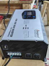
I bought an AMPINVT 2000W (12VDC/120VAC) inverter charger off Amazon (open box but appears new, $350 shipped). I'd like to understand how to safely use it as a backup power supply during power outages. Battery will be 560Ah 12V.lets walk through it.
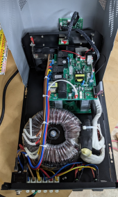
CONFIRMED, via ohm meter and by chasing wires inside. Chassis ground strap is present.Every inverter I have looked at or have the information for has the Chassis Ground, AC input Ground, and AC output ground all tied together. You can check this with an ohm meter.
That sounds right.keep the unit plugged into a grounded wall outlet even when the grid is down (take advantage of the panel N-G bond)
That would work.if using away from grid/wall outlet:
- install a N-G jumper in one of the AC outlets on the inverter (or into the screw terminals, though this leaves more room for error during configuration changes)
That works too.run all loads through a GFCI outlet
Most portable generators do NOT have an NG bond.my neighbor has a cheapo generator I could charge from if needed. I should check if it has a N-G bond and make sure only one N-G bond is connected (generator or my jumper)
Thanks again. I'm now more confident my setup has a lower risk of electrocuting my family while burning the house down.Sounds OK.
Ground current could trip a GFCI. In our case, we're chasing down interference in an analog instrument. Such currents shouldn't be a safety hazard (except in a hospital, where separate grounding is used.)
In the U.S., I think you can find single and two-pole GFCI breakers for 5 mA from 15A to 50A.
At 5 mA, you're protected and you can let go. I think at 30 mA (say 29, so it doesn't trip), you might be left grabbing the wire and unable to let go, but it doesn't kill you.
Yes, copper joined to copper, connected to the ground input and the ground screw sounds good. They don't like us to put two wires under one setscrew for some reason. Except when it is a setscrew "wire nut" rated for multiple wires. Could attach a busbar to the ground screw and land several wires in it. I've used split-bolts to splice wires, with one stripped longer to fit in a terminal.
Solar panel frame ground wire should provide copper path back to ground connection of charge controller. It will also get to the ground rod, but can't only go to a ground rod (unless you want to catch nightcrawlers.)
Switching from utility to battery while hard wired, still have neutral/ground bond at utility panel. Shore power plug of RV/boat, that's where the bond (which hopefully exists) is disconnected when you unplug. And then you hope hot/neutral are wired correctly. "Trust, but verify."
I'm still learning. Dealing with 60 Hz noise in instruments currently, but working with another old timer who has made it his life's work.
I've got a scope with clamp current probe on one wire, and I've set up switches, plugs, transformers, chokes. Oops, my laptop power supply was too close and plugged into the same power strip. Need to unplug, run on batteries, and repeat my noise measurements. I expect to be spec'ing some custom line filters.
The basic functioning of transformers/chokes I've got, but what the hysteresis of BH curves really means for performance is new to me. I managed to measure it with my variac and scope at home, but mapping it to a useful SPICE model is a challenge. Especially when the simulation crashes whenever I push it toward saturation. But my bench tests don't crash
Hysteresis - Wikipedia
en.wikipedia.org
Saturation (magnetic) - Wikipedia