diy solar

diy solar

How stupid is this?

kolek

Inventor of the Electron
Joined
Sep 29, 2021
Messages
430
Hi guys, it's kolek again, the village idiot with zero DIY skills and no qualifications to be doing electrical anything.
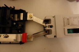
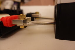
Is it ok to use busbars instead of wire like I'm doing below to make connections? Like below connecting the busbar to the 200A breaker?
1top.JPG
2side.JPG

If you guys approve this, all exposed areas will be covered with shrinkwrap insulation.
I calculated that the cross-section of 2 busbars exceeds the cross-section of the wire I'm using here, so I thought it might be ok.
Using M8 brass nut & bolt for the connection.
The gap between the busbars you're seeing in pic 2 won't be there after I bolt these down to the breaker.
These are solid copper busbars, I have verified that.
No good?
 
Last edited:
I think this should be fine. The resistance of one of the bus bars that came with my LF304 cells is about 0.06 mohm measuring from hole to hole (67mm apart). From that you can calculate the voltage drop at say, 200 amps (V = I * R): 200 * 0.00006 = 0.012 volts. From that, measure power with P = V * I, so: 200 * 0.012 = 2.4 watts. So at 200 amps, this bus bar should be dissipating 2.4w of power as heat.

AFAIK brass is a better conductor than steel.
You don't need the fasteners to conduct, you just want them to tightly hold the surfaces of the two conductors (the Lynx and your bus bar) together.

From a safety perspective I would just make sure to adequately heat shrink the bus bars.
 
@offgrid-curious Thank you very much for responding. Wow that is a lot of information I didn't know about.
Because I'm using 2 busbars on both terminals, the resistance will be half? Actually I will try measuring the resistance on these busbars and see what I get. Gonna go try that now.

Oh and yes I will be careful about making sure they are fully covered with insulation.
 
Last edited:
Because I'm using 2 busbars on both terminals, the resistance will be half?
I didn't notice that you are stacking two bus bars. I don't think that's necessary and may actually add more resistance. I would just use one.

Actually I will try measuring the resistance on these busbars and see what I get.
You won't be able to do that with a standard multimeter. I'm using a YR-1035+ battery resistance tester, which you can get on Ali Express for around 50 USD or so.
 
I didn't notice that you are stacking two bus bars. I don't think that's necessary and may actually add more resistance. I would just use one.


You won't be able to do that with a standard multimeter. I'm using a YR-1035+ battery resistance tester, which you can get on Ali Express for around 50 USD or so.
My logic with 2 bus bars is that it's like a thicker wire. If I only use a single busbar, there's a lot less cross-sectional area of copper making the connection. 60sq mm for my wire, 40sq mm for 1 busbar.
 
It's not exactly like thicker wire though. The two bus bars are not one solid conductor, there will be some small resistance between them. It's just like when you attach two lugs together on a post. In your picture you can see the bottom bus bar is making contact with the breaker and the top one is making contact with the Lynx. The current has to travel between the two bus bars.
 
Hi guys, it's kolek again, the village idiot with zero DIY skills and no qualifications to be doing electrical anything.
Is it ok to use busbars instead of wire like I'm doing below to make connections? Like below connecting the busbar to the 200A breaker?

View attachment 211010
View attachment 211011

If you guys approve this, all exposed areas will be covered with shrinkwrap insulation.
I calculated that the cross-section of 2 busbars exceeds the cross-section of the wire I'm using here, so I thought it might be ok.
Using M8 brass nut & bolt for the connection.
The gap between the busbars you're seeing in pic 2 won't be there after I bolt these down to the breaker.
These are solid copper busbars, I have verified that.
No good?
My only concern would be looks like a height difference between the lynx bus bar and the breaker? Do you have a washer between the bus bars and the bolt, on the underside? To give it enough clamping force that it won't pull away from the lynx bus bar?
 
My only concern would be looks like a height difference between the lynx bus bar and the breaker? Do you have a washer between the bus bars and the bolt, on the underside? To give it enough clamping force that it won't pull away from the lynx bus bar?
Thank you for the feedback. You are correct, there is a slight difference. I am addressing the height difference, there won't be when I bolt them down.
 
It's not exactly like thicker wire though. The two bus bars are not one solid conductor, there will be some small resistance between them. It's just like when you attach two lugs together on a post. In your picture you can see the bottom bus bar is making contact with the breaker and the top one is making contact with the Lynx. The current has to travel between the two bus bars.
I am not saying you're wrong, but it doesn't make sense to me that 2 busbars clamped together create resistance, but individual copper strands which are not clamped together don't.

>there will be some small resistance between them
Why does an electron have to pass from 1 bar to the other? Does the same apply to strands in a copper wire? By that logic, only a single solid piece of copper would ever be acceptable as a connector.
 
@offgrid-curious
A similar example is the JK-BMS ships with 2 connect wires instead of 1 for its connections, presumably to lower costs because 2 thinner wires is cheaper than 1 thick one with the same cross-sectional area. Would you advise JK to use only a single thinner wire, because adding a 2nd creates resistance? Again, not saying you're wrong, I just genuinely don't understand your logic.
 
Hi guys, it's kolek again, the village idiot with zero DIY skills and no qualifications to be doing electrical anything.
Is it ok to use busbars instead of wire like I'm doing below to make connections? Like below connecting the busbar to the 200A breaker?

View attachment 211010
View attachment 211011

If you guys approve this, all exposed areas will be covered with shrinkwrap insulation.
I calculated that the cross-section of 2 busbars exceeds the cross-section of the wire I'm using here, so I thought it might be ok.
Using M8 brass nut & bolt for the connection.
The gap between the busbars you're seeing in pic 2 won't be there after I bolt these down to the breaker.
These are solid copper busbars, I have verified that.
No good?

Are you using the breaker as a master switch?

I would get rid of that breaker and use something else. If that particular connection needs fusing then just convert your lynx distributor to a power-in and connect it the standard way and leave those connections unused.

Unless that is a power-in?

If that isn't an option, make two cables as normal. You're going to need to get all the stuff to make cables anyway.
 
In an earlier iteration of my setup I used battery bus bars to make some connections. I was waiting on more parts. The bars on the disconnect were doubled, and I checked often for heating and voltage drop. No issues noted.
Hey @Q-Dog thanks a LOT for the picture, I'm no expert but that is beautiful work. When you say the bars on the disconnect were doubled, do you just mean where they visibly overlap in the picture, or you actually stacked busbars to gain a thicker connection?
 
@offgrid-curious
A similar example is the JK-BMS ships with 2 connect wires instead of 1 for its connections, presumably to lower costs because 2 thinner wires is cheaper than 1 thick one with the same cross-sectional area. Would you advise JK to use only a single thinner wire, because adding a 2nd creates resistance? Again, not saying you're wrong, I just genuinely don't understand your logic.

It's the way the wires attach to the circuit board on that particular BMS.

Each wire is connected to it's own distinct point.

If you follow through with your setup, just stress test with a full load and see of anything gets warm.

No need to mess around with an ohm meter. The right way is a voltage drop test, not resistance
 
Are you using the breaker as a master switch?

I would get rid of that breaker and use something else. If that particular connection needs fusing then just convert your lynx distributor to a power-in and connect it the standard way and leave those connections unused.

Unless that is a power-in?

If that isn't an option, make two cables as normal. You're going to need to get all the stuff to make cables anyway.
@Checkthisout
Thanks for taking the time to respond.
Since I have no idea what I'm doing, I had my wiring diagram and the individual component recommendations prepared by @ncsolarelectric the CEO of NC Solar Electric LLC, in Statesville, NC.
So if you are going to assert:
>I would get rid of that breaker and use something else.
Please give your reasoning. Thank you!
 
@offgrid-curious Actually I see your point now. I read your point again where you said "It's just like when you attach two lugs together on a post" and a light went on. So then you think I'll get a better connection there with plain ol' wire that has a greater cross-section than a single busbar, right?
 
@Checkthisout
Thanks for taking the time to respond.
Since I have no idea what I'm doing, I had my wiring diagram and the individual component recommendations prepared by @ncsolarelectric the CEO of NC Solar Electric LLC, in Statesville, NC.
So if you are going to assert:
>I would get rid of that breaker and use something else.
Please give your reasoning. Thank you!

Ok so keep the breaker per design but change to cables
 
The copper bus bars are quite okay.
I would skip the brass bolt.
The bolt is there to just clamp.
Go with stainless bolt and nut. Remember a locking washer before the nut.
 
Back
Top