diy solar

diy solar

How to combine AC in and outs of multiple inverter/charge controllers?

You are also availing of Feeder Tap rule by aggregating multiple smaller conductors into #2, so read up on that. It imposes conduit length rules on your installation. Along with ratio between your larger and smaller conductors. This rule governs when you have a larger OCPD than the smallest conductor on a circuit.

You may not be allowed to use this with the EG4 because feeder tap rule requires there to be a OCPD on the smaller conductor. I don't know if the EG4 has a breaker in it to achieve this.

If you use a subpanel you do not need to avail of this rule.
The inverters put out 60amps. I have 63amp breakers between the L1 and L2 individual wires for each inverter line before the wires hit the bus bar AC combiner box. I'm wondering if the issue here is I just need to change out the bus bars I'm using for an actual AC Distribution block?

Also I don't have more than 2 feeder wires in the conduits.
 
Also I don't have more than 2 feeder wires in the conduits.

But you have a T going up into the inner EG4s. There should be 2 wires before and 4 wires after.

AC distribution block would be better than busbar, yes.

Also you have something weird going on with the neutral and line going up separate conduits under the bus bar. You need all CCC and EGC for a circuit in the same conduit or box

BUT. Since you have 4 MCB and distribution block anyway in a box, why not just use a standard North American subpanel at that point, that forces you into a code compliant path that is easier for inspector to understand, albeit maybe bulkier.

Ok. I know I'm going to probably cause you to shake your head in frustration...
So I've got a small breaker box with 63amp breakers for L1(2) and L2(2) lines, and essentially a custom made AC Combiner box which is comprised of four 250amp bus bars combining like wires together into larger wires to feed to the main AC panel.

What I'm hearing from you is, dump the small breaker switch box, dump the custom AC combiner box, and instead install a sub-panel to feed the L1 and L2 wires to double pole breakers, assigning the red an blacks to the breaker so they properly match the correct poles (this will act as a back feed breaker), all the grounding wires to a separate bus bar, and all the neutral wires to their own bus bar, then run my #2 wires from a second set of double pole breakers for the L1 and L2 lines that keep the lines assigned to the same poles in the box to run to the main AC panel, then using lugs run #2 wires from the N & G breaker bars to my main AC Home panel, and this would be safer and more code compliant?
 
Essentially yes. Note the alignment of legs between main and combiner is mostly for bookkeeping to help you figure out how much each leg is drawing. It’s not a safety issue.

The alignment of legs at the combiner box however is important for safety reasons.

You don’t need additional bus bars for neutral and ground. There are neutral and ground bars in the subpanel already. Just wire it all up like a regular subpanel, with solar backfeed. I would put a breaker on the subpanel protecting the wires to the main. Since it is a little safer, and I’ve been told to do that before by designers I worked with.

As for safety/code compliance of subpanel vs terminal block and MCB. Terminal block (or overseas equivalent) and MCB is probably how it is done overseas. You can get UL listed blocks and MCB and enclosure to get a code compliant install that route. If you had more complex routing in mind maybe this approach has more advantages. Since you can have separate buses, isolator switches, relays/contactors etc in the same enclosures.

Your routing here is pretty simple though. If you go with subpanel, the whole system is picked for you as a UL listed set of components. And a U.S. residential building inspector would have seen more solar wiring done this way than with overseas way.
 
Last edited:
I don’t follow...
yes, a panel board or small load center is generally better than a Polaris multi-tap.

The power distribution blocks used to be the go-to solution, but code safety requirements have made non touch-safe things like that an issue with inspectors. Generally they want two levels of barriers to live parts-- dead-front and live-front The power distribution blocks used to be available with an insulated and shrouded assembly, but I haven't seen them around in a long time.
 
Essentially yes. Note the alignment of legs between main and combiner is mostly for bookkeeping to help you figure out how much each leg is drawing. It’s not a safety issue.

The alignment of legs at the combiner box however is important for safety reasons.

You don’t need additional bus bars for neutral and ground. There are neutral and ground bars in the subpanel already. Just wire it all up like a regular subpanel, with solar backfeed. I would put a breaker on the subpanel protecting the wires to the main. Since it is a little safer, and I’ve been told to do that before by designers I worked with.

As for safety/code compliance of subpanel vs terminal block and MCB. Terminal block (or overseas equivalent) and MCB is probably how it is done overseas. You can get UL listed blocks and MCB and enclosure to get a code compliant install that route. If you had more complex routing in mind maybe this approach has more advantages. Since you can have separate buses, isolator switches, relays/contactors etc in the same enclosures.

Your routing here is pretty simple though. If you go with subpanel, the whole system is picked for you as a UL listed set of components. And a U.S. residential building inspector would have seen more solar wiring done this way than with overseas way.
So I wonder what size sub-panel in amps would I want? My main off-grid house panel is planned at 200amps. This guy has a setup with a sub-panel for his system that has two inverters (same as mine) feeding to 70amp double pole breaker in the sub-panel. I've got four inverters...
 
So I wonder what size sub-panel in amps would I want? My main off-grid house panel is planned at 200amps. This guy has a setup with a sub-panel for his system that has two inverters (same as mine) feeding to 70amp double pole breaker in the sub-panel. I've got four inverters...
You need busbar and feeder breaker at 125% of the combined output AC of your inverters. Up to 100A or 125A you can use backfed breakers plugged onto the bus, above that you might need to use main breaker to protect the feed back to your main.

And you cannot put any load breakers on this subpanel, otherwise you will limit the amount of inverter you can put on it. (this follows from 705.12)
 
The power distribution blocks used to be available with an insulated and shrouded assembly, but I haven't seen them around in a long time.
Hmm OK. I thought I saw some references to covered ones on the catalog page.

The uncovered PDBs I thought were UL listed, but maybe there's some extra level of code beyond that. I know livefront relays/contactors are generally not UL508.
 
@zanydroid - There will be no load breakers. Each inverter can put out 54 amps. There will be four inverters, so I was going to put in 70 amp breakers one for each L1 and L2 line, of which there are two of each feeding the breaker box sub-panel. 54 amps at 125% = 67.5 amps, so 70 amp breaker would meet the requirement. Check out my updated diagram below. Let me know your thoughts.
 
Last edited:
Cool. So to clarify you do have 4 current carrying conductors (L and N count, both of them carry the full current) on the conduits under your EG4

Is the #2 to your MSP able to take 67.5 * 2 = 135? I see Copper is 115A @ 75C so no. The subpanel you selected is only 100A

#4 for the 4 CCC conduits

95A (@90C)
85A (@75C)

80% CCC derate = 76A
76A < 85A (cannot exceed 75C rating of subpanel / breakers)
* ???% temperature derate, probably want like 90%? Check the temp derate table for yourself to see what the % is for your climate and installation location

90% -> 68.4A which can take the 67.5A you computed


Another thing to consider is to look up the maximum overcurrent protection on the EG4s and see if they can all be spliced together onto the same giant circuit. You would still probably want some kind of disconnect though for service, probably on an individual inverter basis, and all four disconnects would have to be rated at the full circuit ampacity
 
Cool. So to clarify you do have 4 current carrying conductors (L and N count, both of them carry the full current) on the conduits under your EG4

Is the #2 to your MSP able to take 67.5 * 2 = 135? I see Copper is 115A @ 75C so no. The subpanel you selected is only 100A

#4 for the 4 CCC conduits

95A (@90C)
85A (@75C)

80% CCC derate = 76A
76A < 85A (cannot exceed 75C rating of subpanel / breakers)
* ???% temperature derate, probably want like 90%? Check the temp derate table for yourself to see what the % is for your climate and installation location

90% -> 68.4A which can take the 67.5A you computed


This is from the manual:

EG4.6500EX.Inverter.png
 
Well #4 mathed out OK, but for building wiring NEC unequivocally trumps what the manufacturer says. Can't really tell the inspector "I followed the manual" in that case because the right wire to use varies based on conduit type, wire type, ambient temperature, conduit fill, ...

I assumed AC-in and AC-out were symmetric, also in your diagram you only had one AC connection.
 
Cool. So to clarify you do have 4 current carrying conductors (L and N count, both of them carry the full current) on the conduits under your EG4

Is the #2 to your MSP able to take 67.5 * 2 = 135? I see Copper is 115A @ 75C so no. The subpanel you selected is only 100A

#4 for the 4 CCC conduits

95A (@90C)
85A (@75C)

80% CCC derate = 76A
76A < 85A (cannot exceed 75C rating of subpanel / breakers)
* ???% temperature derate, probably want like 90%? Check the temp derate table for yourself to see what the % is for your climate and installation location

90% -> 68.4A which can take the 67.5A you computed


I bought a 200 amp MSP.

Based on the comments above, are we thinking I need a bigger sub-panel? 125 Amp? And need bigger wires for the trip from the sub-panel to the MSP? 1/0 it would appear at 75C is 150 Amp capacity.
 
Well #4 mathed out OK, but for building wiring NEC unequivocally trumps what the manufacturer says. Can't really tell the inspector "I followed the manual" in that case because the right wire to use varies based on conduit type, wire type, ambient temperature, conduit fill, ...

I assumed AC-in and AC-out were symmetric, also in your diagram you only had one AC connection.
Correct, I'm only using the AC out, this is off-grid. The AC in would be for grid tied systems. My backup generate will use a 48v charger connected directly to the batteries when needed. So I'm not sure what to do about the #4 wires, I guess they are two small when you run two inverters in parallel?
This property is in southern Colorado, at 7,400 feet, so it's generally a colder climate.
 
And I like them better than using busbars to combine my AC wires, good call, I'm ordering these and will update my graphic.

Polaris, the ones I have happen to slip over the insulation of 2/0. But cutting off insulation in middle of a cable, I get two free ends to wire things.

Ampacity rating was something like 400A or more, which makes me feel good when I think about 120% rule for breaker panels.

The inverters put out 60amps. I have 63amp breakers

If thermal-magnetic, 80% of rating means 50A continuous.

Each inverter can put out 54 amps. There will be four inverters, so I was going to put in 70 amp breakers one for each L1 and L2 line, of which there are two of each feeding the breaker box sub-panel. 54 amps at 125% = 67.5 amps, so 70 amp breaker would meet the requirement.

54A not 60A is closer to what 63A breakers carry.

70A breaker x 80% = 56A, so appropriate. Exactly the breaker rating and inverter input current I used. Problem was, with two inverters in parallel and bypassing grid to load (or to PV inverters), current was imbalanced 3:1. That was QO270

I replaced with 63A Schneider multi-9, and much more closely balanced.
I replaced with 60A Midnight/CBI magnetic/hydraulic, even closer balanced.

But you're off-grid and generator less than one inverter's pass through. And DC charger coupled. So not an issue for you.

CBI breakers don't need 80% derating, guaranteed not to trip below 105% of rating so 100% is OK.
Carling breakers guaranteed not to trip below 100% of rating, could use to 95%.

Based on our conversations, I updated the setup like this.

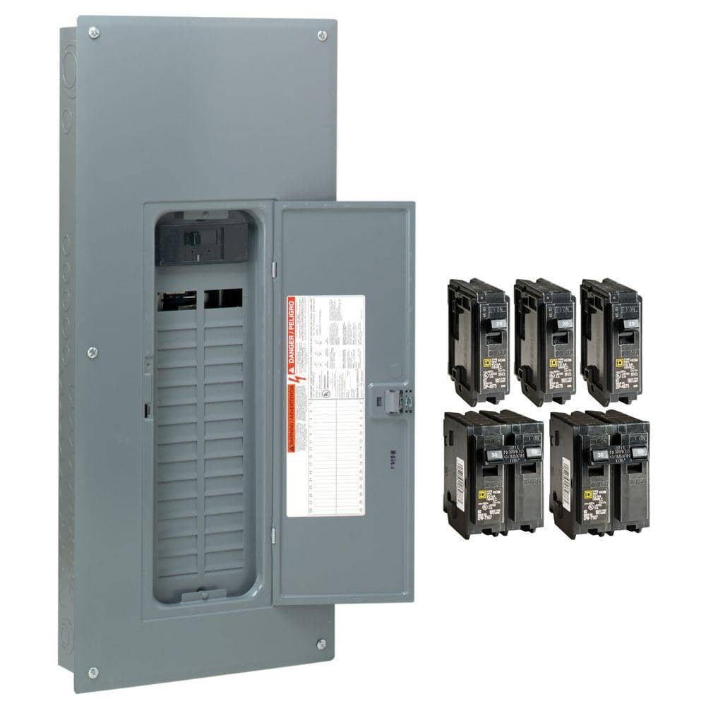
Homeline. I pay more and use QO. It has copper bus for 125A and above, but aluminum for 100A and below.

I bought a 200 amp MSP.

Based on the comments above, are we thinking I need a bigger sub-panel? 125 Amp? And need bigger wires for the trip from the sub-panel to the MSP? 1/0 it would appear at 75C is 150 Amp capacity.

I got one QO value pack. More bucks than Homeline.
You'll find some panels with heavier busbar, like 225A, even though 200A breaker (or 150A also available).
If you want AFCI or GFCI, those are full size.

"plug on neutral" is a new feature so those breakers don't need pigtails. If you get one, double-check torqeuing of busbar. They did a recall over that.
 
Based on the comments above, are we thinking I need a bigger sub-panel? 125 Amp? And need bigger wires for the trip from the sub-panel to the MSP? 1/0 it would appear at 75C is 150 Amp capacity.
You need a subpanel with busbar rating bigger than 125% of your inverter output. I think you need to round up to 150A. So probably a convertible panel with 150A main breaker option available.

200A MSP, 125% * 54 * 2 with 120% rule says you can have ~100A main breaker.

Are you able to limit the output of the EG4 with software configuration? That might help with sizing. Although, also depends on you to trust them to implement it correctly & preserve the setting across firmware update

I'm not sure if it can be limited. I'll look into the 150A sub-panel. The 200A MSP panel has a 200A main shut off, which I assume is split between L1 and L2 as 100A each I assume that is what you mean. It seems the 70A breakers for the sub-pane for each L line is correct, agree?

Any thoughts on wire sizes? From the EG4s to the sub-panel, then from the sub-panel to the MSP?

Really appreciate you time and assistance. Clearly I'm not an electrician...
 
That ought to be 200A each, L1 and L2, with a 2-pole main breaker.
The one you linked is like that.
With only inverters, that 200A main breaker is only a disconnect switch. You could never trip it. Handy with interlocked "generator" breaker to bypass an inverter and use generator instead.
 
Back
Top