diy solar

diy solar

How to Connect Solar To Electrical. First inspection failed…

I feel like I won a prize for getting the right answer! ?

What are your thoughts on the 2/0 between the panels?
The 2/0 is fine, as it's currently being used. And should be fine for the solar installation. The only issue the inspector might have is that the 2/0 is considered an extension of the bus bar. Which would reduce its rating to 195a. Which in turn reduces the amount of solar that can be added.
 
I see how this is apparently a 225A busbar, extended by a 195A 2/0 cable, to another (225A?) busbar. So in a sense it is a 195A system (typically rounded up to next breaker size 200A).

Fed by 200A from one end and 70A from the other, no part of L1 or L2 will ever carry more than 200A (continuously; can have an overload for a while until thermal breaker trips.) I read the NEC group considered this but was concerned relocation of breaker in the future could have current add, so they gave the concession of 120% to make PV possible.

The conductors between the bus bars should be 4/0 for this installation.

That does sound good, so the composite "busbar" is rated 225A.


What I have figured out is that Neutral can carry more than 200A. This occurs if you put in 70A 240V from PV, and load a single phase L1 with 270A. 200A from utility grid feeds the load, 70A from PV backfeeds the load (no point of L1 busbar exceeds 200A), and neutral busbar & cable carries 270A. The utility drop is probably 2/0 (or larger aluminum with same ampacity), and gets heating 270^2 / 200^2 = 1.82x the intended 60 degree rise. Now 109 degrees above 30 ambient = 139 degrees C (for 90 degree insulation.)

Don't do that, and you should be OK.
If your single-phase imbalanced load can never exceed 200A you should be OK. (prefer 160A, 80% of breaker)
 
I don't think the 2/0 lands on a breaker at either end. It's in lugs in the main panel (per the pictures) and I believe it's in lugs in the "sub" panel (per the OP's description)
Of course but it's still the lugs that to need carry the 90c rating.
 
I don't think the 2/0 lands on a breaker at either end. It's in lugs in the main panel (per the pictures) and I believe it's in lugs in the "sub" panel (per the OP's description)


I'd upgrade it, but I think your engineer should be able to calculate the details. Or we can leave it to smarter individuals here.
Given the options, my preference would be 4/0 if the lugs at each end are large enough.

Probably very easy. I'm sure they'll spend significantly longer picking up the wire and driving to the work site.
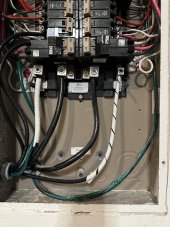
Here’s the inside of the sub panel (where the feeders connect). Let me know if this helps and if you would still update 2/0 wire or if it would work as is.

87ED6DA4-F8BC-4A3B-B39F-50A421BE0D42.jpeg
 
If you put the breaker in the sub nothing needs a changing.
This would be correct for up to 30 amps of solar.
Otherwise, it will depend on how picky the inspector is. (Bearing in mind that they have already failed it once)
 
Back
Top