diy solar

diy solar

How to Wire Breaker/Panel

lboucher26

New Member
Joined
Sep 24, 2022
Messages
59
Hi All

Done DIY home electrical for many years, but this is my first time doing solar.
I'm putting in a Eg4 6k.

I have a Transfer Switch i intend to use to for some loads.

In between the Eg4 output and the Transfer Switch input, i plan to have QOC16UF load center.
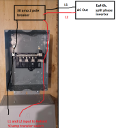
My question is, it it Kosher to wire from the EG4, into 1 of the breakers (30 amp). Then go from the main lug terminals down to the input of the transfer switch?

I'm just not used to wiring incoming power direct to a breaker... And i am not used to wiring an output from the main terminals...
But technically, all the wiring would be protected by the 1 breaker... Other breakers/wires past those breakers would be sized appropriately.

See attached image.

Side question
If i use 30 amp breaker. Will the breaker ever actually trip or would the Inverter shut down prior? Yes i will be putting in a breaker regardless. Just asking.

Thank youLoad Center wiring question.png
 
I am not following the system description. Could you do a diagram showing all the major components. (Inverter, xfer switch, load boxes, etc)
 
I assume this is off grid so please clarify what the transfer switch is doing?

I assume the panel in the drawing is your main loads panel and the wires to the EG4 are the source of power to that panel?

Does the EG4 have a breaker on its output and will it be located close to this panel?
A diagram like @FilterGuy asked for could answer most of the above.
 
Sorry, here is full story. Yes its an off grid setup.

Thanks for such quick responses.

Note: Actually mean Reliant 30 amp transfer switch. The type that only switches the hot.


Overall diagram.png
 
Last edited:
I am not acquainted enough with the EG4 in a grid set up like that. I thought the EG4 was an off grid inverter, If so, does it have a Grid input? Someone with more knowledge of the EG4 can probably give you better advice.
 
In the setup I'm doing in the picture. I never send power back to the grid. Which is what I thought off grid meant? The eg4 does have a ac input to charge battery as well as solar input. Im following the other thread on NG bonding with these units.
 
Side question
If i use 30 amp breaker. Will the breaker ever actually trip or would the Inverter shut down prior? Yes i will be putting in a breaker regardless. Just asking.

A 30A breaker typically requires > 150A to fast trip (in 10's of milliseconds)
Below that, a thermal time constant. Might carry 45A for 10 minutes. 45A x 240V = 10.8kW, doubt inverter will do that. If inverter can put all it's power into a single 120V phase, then might trip the breaker.

Manual for 6kW 120V Sunny Island says, "If you want to fuse individual load circuits in a 120 V grid separately, install circuit breakers with a rated current of up to 20 A: the Sunny Island can safely trip circuit breakers of up to 20 A."

That probably means whatever the overload, fast or slow trip, it can clear the breaker and keep other circuits up. With 50A output it can obviously clear a 30A eventually.

So using typical thermal/magnetic breakers, your inverter may or may not trip a 30A depending on amount of overload. You might find magnetic-hydraulic breakers that could trip faster if desired.
 
filteguy created this document


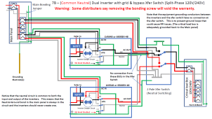
Option 7B looks like something you might use
this the one we are doing for my son's EG4 dual inverter system
First... so that everyone is on the same page, this is 7B from the document.

1672635853373.png


Everyone needs to keep in mind that if you use a transfer switch that does not switch neutral (Such as the Reliance multi-cirucit switches), it creates what I call a common neutral. The output neutral ends up being connected back to the input neutral. People have reported that this works fine for them but the manufacturers say this is unsafe and should not be done.

The manufacturers have not explained why this is unsafe and I have not figured out why it would be.
  • In passthrough mode the input and output neutral is connected together internally, so that must not be a problem
  • In inverter/battery mode the neutrals are not directly connected together, but when the bonding screws are in place, the output neutral is bonded to ground and the input neutral is always bonded to ground through the main bonding jumper in the main panel.... so the input and output neutral are tied together via the bonds and ground.

    So, if the input and output are bonded together all the time anyway, why is it unsafe to bond them together?
 
It doesn't make sense to me either why you wouldn't want them (neutrals) bonded. If they weren't bonded you could have voltage difference between them both causing a hazard and creating a current issue when switching power sources.
 
Morning all

Thanks for responses.
So my original question actually wasn't about NG bonding, which i appreciate is a big deal.
I am following this thread about the NG Bond issues. https://diysolarforum.com/threads/eg4-6000ex-double-ground-neutral.50908/

I think my first question was more simple than people were thinking. (Maybe to simple to need asking? Ohh well, only stupid question is one you don't ask right.)

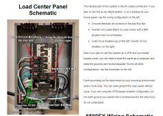
I was just asking if its ok to wire incoming power directly into a breaker. Which now that i study Wills diagram here: https://www.mobile-solarpower.com/48v-complete-system-blueprint.html and copied below. I think i am good.
As for my other question about sending power from Panel to Transfer switch via Main Lugs. Its odd... But is still protected...
I realized that if i ever 2 double up inverters, i would need to bring each inverters power into its own 30 amp breaker. Then have another 30 amp breaker on the output to the transfer switch. Which makes sense..


Wills Diagram.PNG
 
When a plug-on branch circuit breaker is backfed e.g. by generator, there is the possibility of it popping off and having exposed hot leads.
The generator interlock kits I've used have a retention device.
The particular model you showed picture of has the breaker contacts pretty well shrouded so not a concern.

Is a breaker required on output of inverter, if no other sources present? It generally can't trip a breaker of high enough value to be used with its continuous output. How about connecting it to main lugs, or to the higher amperage main breaker as shown in picture?

Or, useful to install interlock between main breaker and backfed branch circuit breaker, so you can use inverter or generator.

Yes, two branch circuit breakers seems like a way to combine two inverters. Again, I don't expect them to be able to trip the breaker, so not sure the point except as a disconnect. (Mine could trip it due to either backfeed from GT PV inverters for grid feeding forward.)

Something funny in that picture - ganged 2-pole breaker on the right, but two black wires coming from it, going out two different conduit. Oh, L1 and L2 coming from two different single-phase inverters. You have one split-phase inverter, might parallel two, which means they have to share current.
 
The generator interlock kits I've used have a retention device.
I actually just installed a Interlock Kit on my Main Panel. It had a Zip Tie to attach the breaker to the "other" top break on the other side. I wasn't sure why this was done, and figured it was the label they had me affix to the zip tie? But now you have me thinking that zip tie was meant to be a retention device... Seems a bit wonky to use a zip tie in that manner, but OK.... Technically Will would be smart to add that on his website/video?

Is a breaker required on output of inverter, if no other sources present? It generally can't trip a breaker of high enough value to be used with its continuous output.
No idea... Manual doesn't say anything. Haven't reached out to Signature Solar... Was just going to add a breaker.

How about connecting it to main lugs, or to the higher amperage main breaker as shown in picture?
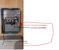
The 100 amp sub panel i am using, shown in picture in first post, doesn't have a main breaker. Was considering adding a separate breaker prior to this panel, and then connecting to the main lugs. Just seemed like more equipment than i really needed. Thus why i am asking if its Kosher to just feed to 1 breaker. Your concern about the breaker Popping Off and having exposed leads, makes sense to me and is enough to make go this route. AKA, have a stand alone 30 amp breaker in its own small box, connect to sub panel main lug, then have another wire set in the main lug that directly feeds the Transfer Switch. All circuits still protected by 30 amp breaker.

1672679997811.png
 
Everyone needs to keep in mind that if you use a transfer switch that does not switch neutral (Such as the Reliance multi-cirucit switches), it creates what I call a common neutral. The output neutral ends up being connected back to the input neutral. People have reported that this works fine for them but the manufacturers say this is unsafe and should not be done.

The manufacturers have not explained why this is unsafe and I have not figured out why it would be.
  • In passthrough mode the input and output neutral is connected together internally, so that must not be a problem
  • In inverter/battery mode the neutrals are not directly connected together, but when the bonding screws are in place, the output neutral is bonded to ground and the input neutral is always bonded to ground through the main bonding jumper in the main panel.... so the input and output neutral are tied together via the bonds and ground.

    So, if the input and output are bonded together all the time anyway, why is it unsafe to bond them together?

I am very interested to figure out why this would be a problem... Because i definitely intend to hook my system up this way as i already have the components and cannot see why its an issue.... Thanks!
 
Is a breaker required on output of inverter, if no other sources present? It generally can't trip a breaker of high enough value to be used with its continuous output
A few days ago I was watching a Mike Holt video of a panel of people and this very question came up. Mike Holt thought the breaker was required and one of the panelists wasn't sure because the inverter is limited. They did not really resolve it in the video. :(
 
A few days ago I was watching a Mike Holt video of a panel of people and this very question came up. Mike Holt thought the breaker was required and one of the panelists wasn't sure because the inverter is limited. They did not really resolve it in the video. :(
I am going to guess that if there is a breaker/fuse on the output of the inverter, there is no requirement for a main breaker in the panel.

In 2007 I had a 100A sub-panel installed by a licensed electrition as part of a major remodel. The main panel has a 100 amp breaker for the line to the sub-panel but there is no 'main breaker' in the sub-panel.....so at least at the time I assume a main breaker was not required. It would be logical to say that if the inverter has a breaker on it's output, there probably does not have to be a main breaker in the panel. However, the NEC sometimes makes blanket rules that do not consider corner cases such as this. Consequently, there may still be some kind of a requirement for a main breaker on the line coming from an inverter even if there is no requirement for a main breaker on a line coming from the main panel.

Having said all that, I would prefer having a main breaker in all sub-panels just for the ability (convenience) to shut down the whole panel without going back to the main panel.
 
Hi All

So was reading around elsewhere. An I'm wondering if the issue with using a transfer switch that doesn't switch the neutral, when using a eg4 6000ex, is that this may result in downstream gfci/arc flash protection devices not working??? Does that make sense?

I read that in one of the reliance transfer manuals it evidently states as much. But I can't find anything like that in the manual for mine.

Has anyone succefully used a gfci on a circuit that is switch through a transfer switch that doesn't switch the neutral when the secondary power source is a eg4 6000ex
 
To use a reliance transfer switch, I'd select a DPDT toggle switch and transfer both line and neutral.
The difference with Reliance is that it makes use of branch circuit breakers in the original panel, or switches the circuit to a breaker inside reliance for generator/inverter.

If you have a sub-panel downstream of an inverter, a GFCI in it should work fine whether neutral is switched or not. Or even if it is bonded to ground in two places prior to GFCI.
 
Back
Top