diy solar

diy solar

Im losing my mind!!

Thanks for all the help today, good to bounce ideas off of one another. Ill report back when i have more data.

Stay well my friends
 
From the Victron SCC screenshot it seems that your solar input is less than 24V? If that's the case then it'll only work with 12V batteries as Victron SCC won't start charging until the input voltage is 5V higher than battery voltage.
 
Victron SCC won't start charging until the input voltage is 5V higher than battery voltage.
Agreed.
But he has 26.5v from 8x 3.3v cells so not sure charging is the issue at the moment (maybe next!).

Also disturbed by the 17v battery shown in Victron display.
 
I wonder if it'll be helpful to disconnect the solar side of SCC entirely and see if the SCC picks up the correct voltage.
Also it's not clear to me from the pictures how the SCC is connected to the batteries. I think there's a shunt on the main positive and both SCC and inverter connect to the shunt?
 
Did you happen to check the power coming into 24v inverter when it was putting out 98v?

OP has a modified sine wave inverter and the 98 volt RMS reading is typical.


A modified sine wave will make a UPS go ape shit. Power strips with surge supressors won't like it either.
 
Last edited:
From the Victron SCC screenshot it seems that your solar input is less than 24V? If that's the case then it'll only work with 12V batteries as Victron SCC won't start charging until the input voltage is 5V higher than battery voltage.
I always set the SCC to 12v or 24v depending on config.
 
OP has a modified sine wave inverter and the 98 volt RMS reading is typical.


A modified sine wave will make a UPS go ape shit. Power strips with surge supressors won't like it either.
My power strip does have a surge supressor. My Killawatt meter also dosent work when plugged in line, strange. I thought the inverter was supposed to manage output voltage to be able to use any AC devices.
 
I wonder if it'll be helpful to disconnect the solar side of SCC entirely and see if the SCC picks up the correct voltage.
Also it's not clear to me from the pictures how the SCC is connected to the batteries. I think there's a shunt on the main positive and both SCC and inverter connect to the shunt?
Correct on the shunt. I added that when I was trying the ElectroDacus BMS, just left it there afterwards. I did try it without the shunt, no difference.

I have also tried it without the SCC connected
 
It seems that multiple people have said to get rid of the power strip.

I agree with them.
 
Help im losing my mind. I started this project months ago and have had limited success. Months ago after watching a few of Wills videos I decided to pickup 8 190ah cells from ali express to build a 24v system. Months later they arrived and the build began. I have 2 Dali BMS's, one an 8s and another 4s, I also have a 21s BMS that Will feateured one of his videos. In addition to that I have a Electrodacus SBMS0.

To date the ONLY configuration i can get to reliably work is the 4s 12v system! Every time I hook up the other 4 cells to make the 8s 24v system the BMS's I have wont charge it and the Giandel 24v inverter dosen't work either! Stupidly frustrating. No matter what 8s BMS I use and I have 3 it just wont work. Im hoping that someone can see something obvious I missed.

Hardware list
4, 100w solar panels
Victron 150/35 SCC (set to 24v)
8, 190AH Lifepo4 cells from ali express, all verified at 3.3v per cell 26v for pack
Victron 200A battery protect (set to 24v)
Dali 8s 100a BMS, Ebay 21s BMS, ElectroDacus SBMS0, Dali 4s BMS
Renogy 1000w 12v inverter, Giandel 24v 2000w inverter


View attachment 9376View attachment 9378View attachment 9379View attachment 9380View attachment 9381
View attachment 9382
THIS INVERTER IMAGE ABOVE SHOWS 26.5V, SORRY THE DISPLAY FLICKERS

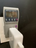
THIS IMAGE BELOW SHOWS MY POWER STRIP CONNECTER TO THE 24V INVERTER, IM NOT SURE WHAT THESE SYMBOLS MEAN BUT I THINK ONE IS GROUND? NO POWER AT POWER STRIP
View attachment 9383
Perhaps a bad battery that breaks down underload, registers ok with no load?
 
I always set the SCC to 12v or 24v depending on config.

Yes, but your solar panels need to put in voltage that's 5V higher than the battery voltage for it to start working. For example, if your battery voltage is 25V than your solar panels need to put 30V or higher before SCC start charging your battery.
 
Well yesterday when the photos were shot it was a sunny day and i have 5, 100watt panels so I cant imagine they wouldn't be capable of that.
 
Well yesterday when the photos were shot it was a sunny day and i have 5, 100watt panels so I cant imagine they wouldn't be capable of that.

How do you connect the panels together? Are they all in parallel? If so, you don't have enough voltage to feed a 24V system. You'll need to have at least 2 100W panel in series to have high enough voltage.
 
I cant remember, ill verify them in a few hours. If I remember right I have 2 100w panels using mc4 2 to 1 Y connectors and the other 2 are just like that for a total of 4. Then I have one random 100w panel as well. They all go into a combiner box.
 
Sounds like you have them all in parallel. You'll need to series connect the pairs and get one more panel (or disconnect the lone 100W). You can still use this configuration for 12V system as your SCC will properly convert the voltage according to your battery voltage.
 
OK wired the 4 panels in series, voltage up to 44v, Will try hooking up the 8s to see if charging will take place.

IMG_2837.PNGIMG_3444.JPGIMG_4863.JPG
 

Attachments

  • IMG_2999.JPG
    IMG_2999.JPG
    66.4 KB · Views: 5
Last edited:
OP has a modified sine wave inverter and the 98 volt RMS reading is typical.


A modified sine wave will make a UPS go ape shit. Power strips with surge supressors won't like it either.
Ok so now that I have wired the 4 panels in series and its now charging the 8S into the 24v inverter. It seems to be outputting power now but as quoted above it seems to make the power strip surge supressor and the KillaWatt meter wacky. My laptop is charging through the KillaWatt meter but the meter reads zero for all measurements. Is this because the inverter is a modified sine wave inverter vs a Pure sine wave inverter?

Again thanks to everyone for all their help, Im almost there!
IMG_2999.JPG
 
Connect a fan to the inverter output (the type you use to stay cool in summer). If it buzzes loudly, the inverter is definatly the modified sinewave type. Some equipment really HATES MSW inverters, and won't work properly, which is probably what the surge protector and Kill-A-Watt are doing.

With regards to the display on the Giandel inverter, if the OP can read it fine, its just multiplexing making it difficult for his/her camera to capture the display. Multiplexing is a trick used to reduce the power consumption of a display by only lighting one segment at a time in rapid succession. thanks to persistence of vision, our eyes can't tell the difference, just the same as they are tricked by the rapid stream of still images that make up a television picture, but a camera with a high shutter speed can pick it up, making the display look faulty.
 

diy solar

diy solar
Back
Top