diy solar

diy solar

Inverter capacitor charging spark!

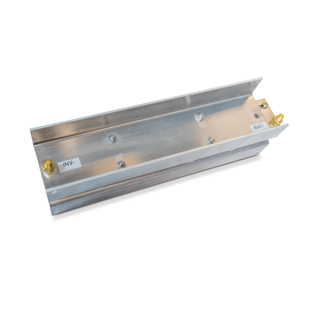
This is what I do:
https://diysolarforum.com/resources/inverter-disconnect-switch-with-precharge.60/

A couple of notes:
1) I like this better than a push-button because even if you rotate the switch quickly, you will at least partially pre-charge the caps, but it is easy to forget to press the push-button.

2) When I first developed the design in the resource, I was worried about the case where someone leaves the switch on pre-charge *and* has the inverter on. In this case I was worried about a lot of current going through the pre-charge resistors and overheating them. Consequently I put the PTC resisters in to act as a limiting device to prevent any problems. I have since tried this on three different inverters and if you leave the switch on pre-charge while the inverter on, the inverter detects low battery and does not fully turn on. Consequently, the pre-charge resistors never heat up. I am debating whether I should remove the PTC from the design but I don't know if the sample of 3 different inverters are representative of all inverters.. (I did not put the PTC in the last build I did because the inverter I was using did not need it)
 
Last edited:
Nothing about pre charging in my Victron Manual. I'm running a 12/3000/120 Multi Plus. Seems to me if it was a big problem Victron would say something about it.

Greg
Victron isn't a cheapie Chinese manufacturer so you can expect decent quality components. Try dead dropping a crappy 2000uF electro capacitor onto a 200 amp power supply 30 times and let me know how it performs after that ...

*edit*
added 'dead'
 
Nothing about pre charging in my Victron Manual. I'm running a 12/3000/120 Multi Plus. Seems to me if it was a big problem Victron would say something about it.
In the inverter, the only thing that is taking the current is the capacitors and wires (and *possibly* a shunt) so it is not a surprise the inverter manual does not mention it. Several folks have commented that the inrush is bad for the capacitors. I can not say they are wrong, but I am not sure how the current would damage them.

The surge current through the battery is probably not good for the LiFePO4 cells, but my guess is the surge is so short the cells handle it with little or no damage.

Where things get 'interesting' is the surge current through the BMS, In this case you are putting a momentary but monster current through the FETs of the BMS. In many cases, the BMS will detect this as a short circuit and shut off. (You can see this in a few of @Will Prowse videos). Even if the BMS does not shut off, the surge through the FETs can damage them.
 
Last edited:
but I am not sure how the current would damage them.
Legs of capacitors are relatively thin, so are PCB tracks ... large currents, even momentarily, could cause enough heating effect to damage them?
 
Damage can be hidden within the capacitor too. The joint between the leg and the sheet can be degraded, oxides can form on the foil, both increasing the ESR significantly and the latter reducing the capacitance too. Quality capacitor manufacturers provide this info, I'm sure a Google search will turn up heaps of info if anyone wants to do more reading about it.

I've mentioned it before but there is a class of capacitor specifically for high current flows, pulse capacitors. You'll find them in applications like electric fence controllers, very high ripple current applications etc.
 
2) When I first developed the design in the resource, I was worried about the case where someone leaves the switch on pre-charge *and* has the inverter on. In this case I was worried about a lot of current going through the pre-charge resistors and overheating them. Consequently I put the PTC resisters in to act as a limiting device to prevent any problems. I have since tried this on three different inverters and if you leave the switch on pre-charge while the inverter on, the inverter detects low battery and does not fully turn on. Consequently, the pre-charge resistors never heat up. I am debating whether I should remove the PTC from the design but I don't know if the sample of 3 different inverters are representative of all inverters.. (I did not put the PTC in the last build I did because the inverter I was using did not need it)

But if there's other loads than the inverter the PTC is still useful as they usually don't have LVD unlike the inverter.

NB: in the last page of the ressource the last diagram title should say 48 V instead of 24 V. Also most of the resistors values aren't standard and will be hard to find and more expensive, you should pick from the E12 series (or the E24 one if you really need closer values) ;)
 
I just did the delivery(smoke) test on my 1500watt@24volt inverter.
I don't have batteries yet so I used my powermax 30amp converter.
the 30amp fuse between the 2 survived.
Wish I had a clamp meter to see what the inrush was.
 
Wish I had a clamp meter to see what the inrush was.
I doubt very much you'd see this inrush with a clamp meter, maybe a modern oscilloscope. These unrestricted inrush currents would only last for milli-seconds, certainly less time than it would take to blink.
 
Last edited:
Any DSO + shunt works a treat., just don't under-estimate the rating of the shunt required.
 
Legs of capacitors are relatively thin, so are PCB tracks ... large currents, even momentarily, could cause enough heating effect to damage them?
OK.... I would not have expected such a short surge to effect the traces or component leads.
 
But if there's other loads than the inverter the PTC is still useful as they usually don't have LVD unlike the inverter.

NB: in the last page of the ressource the last diagram title should say 48 V instead of 24 V. Also most of the resistors values aren't standard and will be hard to find and more expensive, you should pick from the E12 series (or the E24 one if you really need closer values) ;)
good points. I updated the resource to address these points.
 
I doubt very much you'd see this inrush with a clamp meter, maybe a modern oscilloscope. These unrestricted inrush currents would only last for milli-seconds, certainly less time than it would take to blink.
My Fluke clamp has and inrush button. It would catch it.
 
As discussed in another thread, the main reason i use precharge in my system is to prevent arc welding my contactor contacts closed. Nothing to do with inverter/battery/bms protection. (my BMS never carries load current)
 
This pre-charge is not to save BMS or batteries.
It's more to save life for circuit breaker and electrolytic capacitors that installed in inverters.
Of course system will work without pre-charging, but this inrush current not adding life to system at all.
 
Is this same problem solved by a product like the BattleBorn CSL500?

I like that the CSL500 doesn't require remembering to precharge/knowing if the capacitors have dissipated, but I'm curious what the other pros and cons are.

One thing that I find suspicious about the CSL is that my inverter will not be connected to ground (directly) and since it's producing 120VAC I feel uneasy about that. Maybe the chassis ground point is still connected directly to ground, but then it could cause excessive current across that path.

If I knew what the CSL was perhaps I'd feel more confident, perhaps I'll have to disassemble it...
 
More important than the spark is what is that inrush current doing to the contacts in your switch and to your BMS?

I have an 82 ohm, 25W resistor wired in parallel with a 200A switch in my system.

To connect:
  • Turn off power switch on Inverter
  • Open 200A switch
  • Connect battery to inverter
  • Wait 10 seconds (probably serious overkill)
  • Close 200A switch
  • Turn on inverter.
That resistor is able to handle a continuous dead short to ground of my 24V battery. Approximately 312 mA max current or 8W of power dissipation. I could turn the inverter on without the 200A switch being closed and nothing bad would happen. I could open the 200A switch while the inverter is in use and nothing bad will happen. I don't even need a heat sink on the resistor.

Scale the resistor value accordingly for a 12V or 48V system. 22 ohm for 12V, 330 ohm for 48V. My resistor selection criteria is a value that sets max power dissipation at ~ 1/3 of the resistor power rating (8W is my target).

The resistor I am using costs about $4 from digikey.

 
Last edited:
We all know that when you initially connect an inverter to power you get a spark as the capacitors charge up. For bigger inverters this spark is pretty significant. If the final connection is to your battery it means you get a tiny "weld" on the battery terminal each time you do this. I, for one, don't like to see these blemishes on my expensive LiFePO4 battery terminals. I'm wondering what folks do to avoid this - or am I just being too picky? Seems like you're going to get these marks on either the inverter or the battery terminals one way or the other unless someone has a solution that works for them.
hi, any low power tungsten bulb 110vac (40-60watts) will work when in serie with your cable (if the battery is less than 110v) for few seconds.. on a low voltage battery, a 20w buld work well because filament resistance is lower when the bulb don’t light.. me, i don’t like big sparks and it’s not recommended for big capacitors (when you hope a long life).. the usage of switch? ..think about the contact switch add a resistance and you want to have a minimum voltage drop!
hope that may help you..
Marc
 
I know this has been mentioned here many times.
Simple and inexpensive.
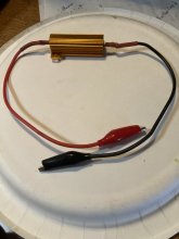
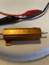
I only need this to absorb inrush if I have to disconnect my battery from my Samlex 2000w 24v inverter. Quick connect the resistor between battery and inverter then connect battery. Done, remove and keep near the battery for the next time you have to disconnect battery. (No reason to disconnect that often) I got two for $5 simple solder the wire/ clips.
Remember that as long as the inverter is connected to the battery the capacitors remain charged even if the inverter is switched off.

9C4D319F-1722-4250-BA60-7C5CAA7CA8C2.jpegE3845C33-09CC-4D49-83D2-A942C5CBBDAB.jpeg
 
I have the same 50-ohm resistor (as seen in mrnatural22 photo )connected in series with a push-button switch. These two are then connected across the terminals (in parallel) of my 100 amp circuit breaker that is in series with the positive lead of my battery.

Before I switch on my breaker, I hold the push button switch for about 5 seconds then let go of the button and switch the breaker on.

I don't ever see any sparks anymore and when testing the resistor current when pushing the button, there is very little and prevent that spark. - It works for me!
 
Back
Top