diy solar

diy solar

Is there a better MC4 tool?

You guys are driving me crazy! Staubli. that is the company that now owns/manufactures what was the original MC4 connector and tools to crimp, tighten and take apart.


If you want to purchase originals and spend more, then by all means.

THERE IS NO STANDARD FOR KNOCKOFFS OF MC4 CONNECTORS. JUST COPIES. SOME ARE BETTER THAN OTHERS.

PROCEDURE:

Buy a pair of MC4 tools. In every case, they are heavy plastic and are used to take the connectors apart and to screw the wire connector tight to the body of the MC4 and unscrew them.

Buy MC4 connectors. Buy the original Staubli or a very good knockoff. Some knockoffs are so cheaply made that they have poor O-rings for waterproof seals, and very thin metal connectors as well as being out of physical spec by enough of a size that they only fit themselves together.

Purchase an MC4 crimping tool. You need a specific tool to crimp PV wire to the MC4 metal conductor pins.

I already posted above recommended tools. I have removed and made hundreds of MC4 connections using Staubli and good knockoffs.

You don't need zip ties or other fancy stuff. You need to be able to cut and strip PV wire 12 awg and 10 awg.
 
You guys are driving me crazy!
Good, because MC4 connectors drive people crazy. All your comments are around grabbing the connector crimping the contact and snapping it together. Never had a problem there ever. That plastic tool works well if the connector is brand new, and it's been installed for an hour our less, you can generally get the thing to pop apart without too much difficulty, though it doesn't like to give at all. The problem is getting the damn things apart after they've been in the 115F heat, a dust storm , followed by rain, and another dust storm. A low tolerance tab & hook lock system with a rigid plastic body is so sub-optimal for anything exposed to the elements, it is stunning to me that anyone would have engineered or adopted it for outdoor use.

I point again to the RF 'N' connector, designed for outside use. I've *never* had one seize ever. Or even the gland side of the MC4 itself. If you simply replaced the stupid clip system with a threaded cap, like a high quality inline automotive fuse holder (Not a push and turn), or a simple coaxial cable connector you'd get the same mechanical security and be able to get the damn thing apart once you unscrew it. Whoever thought MC4 was a good idea had obviously never climbed up on a roof and replaced any old wiring, they just came up with something stupid that met a specification: contact rating, double sleeved with O rings for outdoor, and mechanically secure. Obviously did not look at any proven designs for ideas. Obviously did not ask any technicians with experience working with this kind of stuff.
 
Snap ring pliers are still my go to tool for disconnecting them.
I tried using the plastic tool on some panel connectors that were together for ~8 months a few months ago and chucked it in a fit of rage while stomping to the garage to grab my Knipex snap ring pliers.
 
Whoever thought MC4 was a good idea had obviously never climbed up on a roof and replaced any old wiring, they just came up with something stupid that met a specification: contact rating, double sleeved with O rings for outdoor, and mechanically secure. Obviously did not look at any proven designs for ideas. Obviously did not ask any technicians with experience working with this kind of stuff.
These are the engineers that probably put together the freeway system. 😁

That being said, I don't have a design background. I'm more of a McGyver kind of a DIY-r. What would be the process for designing and creating a new connector? Taking into account what technicians are experiencing out there.
 
US Freeway's are not that bad overall, we had Germany's autobahn as a template when Ike started the project. The problem is running them thru a town in place of cobblestone streets with no room and too many ramps, and skimping on Real Estate, followed by explosive growth that was totally unplanned (un-plannable really) for. The LA freeways are actually very good, they just have too many cars, 100lb of potato's in a 50lb bag. The northeast suffers from the existing infrastructure problems, on top of that.

RE: Designing a connector.

1) Find something already out there
2) If #1 fails find something close and modify it.
3) Use your brain
4) Test what you come up with in a real world scenario.

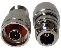
Outdoor connectors have been around since the 40's and 50's. Anyone who ever had an old TV antenna with 300 Ohm cable and butterfly nuts can tell you it's sub optimal. The 'N' connector I keep referring to is an amazing design:

1719792061573.png

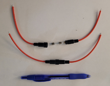
The contacts are more suited to RF signals, lots of concern about coax/shielding the signal, but this basic barrel design is used in multiple RF outdoor connectors. The threaded barrel design is vastly superior to requiring a special effing tool. Take for example this 250v 10A Fuse holder, 10 pak for $5:

1719792475019.png

For an outdoor connector, maybe 20A, you will want to be slightly larger and have o-ring seal and double insulation. You could literally take the basic MC4 design, same contacts and replace the stupid clips with male threads on on side and a female ring/cap on the other. Keep it all plastic. Lose the removal part of the tool. Threaded cap keeps dust and dirt out, and you will never have an issue getting them apart. If anything it would be *less expensive* and more reliable, but no . . .

Some pr*ck decided to make a proprietary connector that was difficult to use so they could be really cool and have a "solar" connector, and sell custom tools. I used to work with a company (Aerospace Contacts) that machined the actual contacts (The metal part that conducts, inside the connector). Stunning what some of the "engineers" come up with, I mean like things you cannot actually even make, not to mention not understanding the properties of the material used to make them. Why should the solar industry be any different?
 
US Freeway's are not that bad overall, we had Germany's autobahn as a template when Ike started the project. The problem is running them thru a town in place of cobblestone streets with no room and too many ramps, and skimping on Real Estate, followed by explosive growth that was totally unplanned (un-plannable really) for. The LA freeways are actually very good, they just have too many cars, 100lb of potato's in a 50lb bag. The northeast suffers from the existing infrastructure problems, on top of that.

RE: Designing a connector.

1) Find something already out there
2) If #1 fails find something close and modify it.
3) Use your brain
4) Test what you come up with in a real world scenario.

Outdoor connectors have been around since the 40's and 50's. Anyone who ever had an old TV antenna with 300 Ohm cable and butterfly nuts can tell you it's sub optimal. The 'N' connector I keep referring to is an amazing design:

View attachment 225728

The contacts are more suited to RF signals, lots of concern about coax/shielding the signal, but this basic barrel design is used in multiple RF outdoor connectors. The threaded barrel design is vastly superior to requiring a special effing tool. Take for example this 250v 10A Fuse holder, 10 pak for $5:

View attachment 225729

For an outdoor connector, maybe 20A, you will want to be slightly larger and have o-ring seal and double insulation. You could literally take the basic MC4 design, same contacts and replace the stupid clips with male threads on on side and a female ring/cap on the other. Keep it all plastic. Lose the removal part of the tool. Threaded cap keeps dust and dirt out, and you will never have an issue getting them apart. If anything it would be *less expensive* and more reliable, but no . . .

Some pr*ck decided to make a proprietary connector that was difficult to use so they could be really cool and have a "solar" connector, and sell custom tools. I used to work with a company (Aerospace Contacts) that machined the actual contacts (The metal part that conducts, inside the connector). Stunning what some of the "engineers" come up with, I mean like things you cannot actually even make, not to mention not understanding the properties of the material used to make them. Why should the solar industry be any different?
The N connector is a wonderful connector but personally I prefer DIN 😎

Just a little RF humor

I agree with replacing the clips. Everything else about the connector isn't that bad. Just those freaking little snap and clips.
 
I had a couple of these on some used panels... I actually just cut the ends of the locking tabs off a couple, so its just a flat blade in the hole to help with alignment. Once the are pressed in there really isn't anything that will try and tug them apart anyway. Spot of hot melt glue would be better than those effing locking tabs.
I used a small flat blade. Works every time. I haven't tried the split ring plyers. Not sure how they would get in the tight space.
 
I think its a great connector it just require replacing from time to time. Every wire failure I have had on the pv side has been with a mc4 connector but it only takes a minute or two to cut the old end off and replace it so its not a big deal. Sometimes I just replace the connector itself. They are easy to work with if you get good removal tools. I don't have a magic place to buy them I just got lucky over the years collecting up different ones (from buying directly or with them being included with connectors I bought) and the ones that work best I keep handy.

One thing I think its time for is a mc4b connector with the b meaning big. Its time these things moved up to 6awg size at least. PV voltages are higher and the amps being expected from them has reached a new level. The connectors need to evolve for this.
 
Good, because MC4 connectors drive people crazy. All your comments are around grabbing the connector crimping the contact and snapping it together. Never had a problem there ever. That plastic tool works well if the connector is brand new, and it's been installed for an hour our less, you can generally get the thing to pop apart without too much difficulty, though it doesn't like to give at all. The problem is getting the damn things apart after they've been in the 115F heat, a dust storm , followed by rain, and another dust storm. A low tolerance tab & hook lock system with a rigid plastic body is so sub-optimal for anything exposed to the elements, it is stunning to me that anyone would have engineered or adopted it for outdoor use.

I point again to the RF 'N' connector, designed for outside use. I've *never* had one seize ever. Or even the gland side of the MC4 itself. If you simply replaced the stupid clip system with a threaded cap, like a high quality inline automotive fuse holder (Not a push and turn), or a simple coaxial cable connector you'd get the same mechanical security and be able to get the damn thing apart once you unscrew it. Whoever thought MC4 was a good idea had obviously never climbed up on a roof and replaced any old wiring, they just came up with something stupid that met a specification: contact rating, double sleeved with O rings for outdoor, and mechanically secure. Obviously did not look at any proven designs for ideas. Obviously did not ask any technicians with experience working with this kind of stuff.
The plastic MC4 tool works just fine regardless of the age and weathering of the connector if these conditions are met:

1. Its the same plastic tool sold by your MC4 maker that worked great originally. Again, there are no standards for knockoffs.
2. Always use dielectric grease in MC4 connectors when putting them together. This helps take them apart no matter the age and offsets some of the aging that can occur over time with the O-rings that are on an MC4.

But if your plastic tool just doesn't work and the MC4 are old, I take 2 seconds and just cut them off and install new ones. I don't waste time prying them apart.
 
But if your plastic tool just doesn't work and the MC4 are old, I take 2 seconds and just cut them off and install new ones. I don't waste time prying them apart.
I rest my case. You might as well use a wire nut or butt splice. You will get a better connection, and you have to cut it off anyway. And you are really good if you can re-crimp an MC4 in 2 seconds. :ROFLMAO:
 
I rest my case. You might as well use a wire nut or butt splice. You will get a better connection, and you have to cut it off anyway. And you are really good if you can re-crimp an MC4 in 2 seconds. :ROFLMAO:
With the right tools its about that fast.

1. I cut the wire with the cutter section of the stripper (instant) thus instantly removing the bad connector.

2. Shove the wire end into the stripper and squeeze it and it instantly strips it to the right length. (Got to love automatic wire strippers)

3. I slide the new plastic nut and compression onto the wire (2 seconds or so)

4. Shove the stripped end into metal contact and crimp it using the special crimper that's designed for it (2 to 4 seconds)

5. Shove the finished contract into the house and tighten the nut onto the housing using the plastic removal tool since its designed to slip when its tight (5 seconds tops I guess)

So 15 seconds if your trying for speed.

Either way its very easy. I like the connectors personally.
 
Last edited:
That is either the result of a bad crimp or the failure of the weather seal. I use dielectric grease when assembling connectors. Normally there is an
o-ring in the connect and I am not seeing one here.
 
That is either the result of a bad crimp or the failure of the weather seal. I use dielectric grease when assembling connectors. Normally there is an
o-ring in the connect and I am not seeing one here.
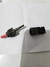
Thats because its not unscrewed. The cap is still fully threaded on it it. It snapped in half when it melted.
 
Thats because its not unscrewed. The cap is still fully threaded on it it. It snapped in half when it melted.
Heat due to bad crimp or poor connection between the male and female connections dues to moisture intrusion which resulted in corrosion. What gauge was the cable. Most cables are 10awg which should handle any panel current barring any other faults or issues Normally heat is the result of current across a resistance???
 
The contacts in the MC4 are best described as weak. They are too thin for the current IMNSHO. Further both plug and socket are stamped and rolled foil. If it heats up much it will change shape. It should be a solid or fully wrapped and bonded pin/plug and a 3 or 4-way wiping socket/receptiical. Heat treated copper alloy would be nice. We might be shoving a sustained 15A thru the thing. I mean how does the contact in an MC4 compare to a standard Nema 5-15? Euro plug? The thing is junk.
 
Agreed there must be better ways.
And yet they are the standard and there are millions in use all over the globe…
 

diy solar

diy solar
Back
Top