diy solar

diy solar

Is there a difference if I daisy chain batteries or connect them to a buss bar for parallel connection?

ctsit

New Member
Joined
Mar 31, 2022
Messages
33
Hi all,

I have the following question:
I want to create a off grid system that will comprise of the following components:
1. Victron Multiplus ii 5000va (1 at the begging and then maybe add another one, otherwise I will go with the 8000va)
2. Victron Lynx Power in (Initially 1 and later maybe a second one depended on the batteries I connect)
3. Victron Lynx Distributor (1 item)
4. Victron Lynx Shunt (1 item) (not sure about this maybe I will go with the simple shunt)
5. Victron Cerbo GX (1 item)
6. SmartSolar 150/85-Tr VE.Can (most likely 1 but maybe a second one later on)
7. 5kwp Solar (this the option of adding 2.2kwp)
8. Necessary fuses and disconnect where appropriate (I will seek an experts opinion on this)
9. Power Queen 48v 100ah batteries, most likely 4 for a total of 19.2kwh and here is the question.

The concept is to connect all Batteries directly to the Lynx Power In and not daisy chain them.
In the Power Queen website they state:
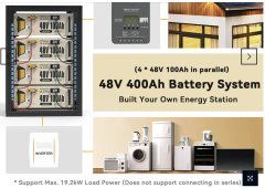
"Power Queen 48V Lithium Iron Phosphate Battery supports 4 batteries in parallel (4P), easily set up a 48V 400Ah Large Solar Battery System with 19.2kWh large capacity, support Max. 19.2kW Load Power (does not support connecting in series), meets the power requirements of a wide range of application scenarios. Allowing you to have your own energy station."
Does the above statement refer to daisy chain the batteries or even if they are independently connected to a buss bar which is the Power In?
Thank you in advance for your time
 
You can take the power from the positive of the first battery and the negative of the last battery, all of the energy will be shared.
 
First off @BiduleOhm you are correct the way I mention daisy chain is confusing.
So to phrase it correctly is there a difference connecting in parallel the batteries by using one of the two positive poles and connecting to the other batteries positive and one of the two negative poles and connecting it to the other batteries negative, than connecting one of each batteries positive poles to a positive buss bar and one each batteries negative poles to a negatives buss bar?
 
If done according to the page 19 diagrams, then no, it's equivalent, you won't see any difference ;)
 
Ok then that means that indeed the limit is 4 batteries in Parallel.
Thank you
 
I recommend you consider Bus bars and Fuses:
Each battery connects to two main bus bars, one POS one Neg Size bus-bar to max expected loads x 1.25 (or more for future expansion).
The POS connection to the bus bar from each battery to be made with a bidirectional 1P 125A DC breaker, AND a 125A Class-T fuse on each battery.
The DC supply to the Inverter(s) from the two bus bars then each have a Class-T fuse (size to max load x 1.25) AND a 2P bidirectional DC Main breaker.

This set up method not only provides fused protection for each battery, but also facilitates maintenance and upgrade work, as you can control the energy supply from any one battery individually without shuting down the whole system, a battery can be removed safely or an additional battery added without shutting down the inverter(s). The main 2P breaker will allow you a single point of control to shut down the entire ESS in case of emergency.
Depending upon the rules where you live, some of the above will be code requirements, in either case it is a safe and efficient way to control your energy storage system.
 
Last edited:
Does the above statement refer to daisy chain the batteries or even if they are independently connected to a buss bar which is the Power In?
Thank you in advance for your time
Paralleling to busbars allows each battery to be individually fused and functionally independent from the others.
Also each battery has far less joinery and thus less path resistance as opposed to "daisy chain with diagonal feeders".

Its true that the path resistance for "daisy chain with diagonal feeders" is roughly equal between the batteries but the path resistance for each battery is significantly higher.
Since the batteries are not path independent larger wires and a larger fuse must be used.

Each battery in a "daisy chain with diagonal feeders" can be fused independently at the expense of even more resistance for each battery.
 

Attachments

  • parralleling_methods.txt
    902 bytes · Views: 32
The difference between the methods is roughly analogous to factory manifolds and combined exhaust vs headers and dual exhaust.
 
Last edited:
However, unlike the exhaust system, removal of a single battery (cylinder exhaust) while the rest of the system is running, is a common requirement!
LOL.
 
I recommend you consider Bus bars and Fuses:
Each battery connects to two main bus bars, one POS one Neg Size bus-bar to max expected loads x 1.25 (or more for future expansion).
The POS connection to the bus bar from each battery to be made with a bidirectional 1P 125A DC breaker, AND a 125A Class-T fuse on each battery.
The DC supply to the Inverter(s) from the two bus bars then each have a Class-T fuse (size to max load x 1.25) AND a 2P bidirectional DC Main breaker.

This set up method not only provides fused protection for each battery, but also facilitates maintenance and upgrade work, as you can control the energy supply from any one battery individually without shuting down the whole system, a battery can be removed safely or an additional battery added without shutting down the inverter(s). The main 2P breaker will allow you a single point of control to shut down the entire ESS in case of emergency.
Depending upon the rules where you live, some of the above will be code requirements, in either case it is a safe and efficient way to control your energy storage system.
First of all, thank you for the detailed explanation.
The lynx distributor, which is one of the components I intend to use, provides the ability to fuse each connection. Maybe instead of a Lynx Power in I will use another distributor (on the other hand there are videos that show how to fuse the lynx power in). But I didn't thing of an isolator for each battery because, as shown above, each battery has it's own breaker, wouldn't that be enough for isolation?

For the connection between the distributor and the Inverter, indeed, I was planning of placing a fuse with cut off Circuit Breaker.
Alternatively (although more expensive) use Victron Lynx Shunt which can be Fused accordingly and use a separate circuit breaker.

Again thank you for your help.
 
Maybe instead of a Lynx Power in I will use another distributor (on the other hand there are videos that show how to fuse the lynx power in).
Use a power-in.
The fuse is supposed to be as close to the battery positive terminal as possible.
That is the where the pixies are most angry.
 
Use a power-in.
The fuse is supposed to be as close to the battery positive terminal as possible.
That is the where the pixies are most angry.
The Lynx Distributor takes MEGA fuses, the Power In requires modification for a MEGA fuse.
 
I'm currently running four separate 12v battery packs (Eve lf280K cell packs) into a modified Lynx power In buss unit with added megafuses for each battery pack. It's working just fine, with very slight variances of power in and out. I need to go back over all my connections now that I broke down and bought a torque wrench. Then I expect the power levels to be more even. Regardless of uneven power transmission, I'm technically not going to loose any overall storage capacity, because if one battery pack gets too high or too low, the bms can stop charging or discharging, and the other packs continue to provide functionality. Obviously, this is not the IDEAL, but practically, it's a non-issue. The only way it could become an issue is if each bms is maxed out on amperage, but this never happens in reality. For example, my system technically can output 50 amps per pack, for 200 amps. If I was drawing a full 200 amps, and one pack went offline, then my system capacity would be reduced to 150 amps, but, again, that never happens.
 
I recommend you consider Bus bars and Fuses:
Each battery connects to two main bus bars, one POS one Neg Size bus-bar to max expected loads x 1.25 (or more for future expansion).
The POS connection to the bus bar from each battery to be made with a bidirectional 1P 125A DC breaker, AND a 125A Class-T fuse on each battery.
The DC supply to the Inverter(s) from the two bus bars then each have a Class-T fuse (size to max load x 1.25) AND a 2P bidirectional DC Main breaker.

This set up method not only provides fused protection for each battery, but also facilitates maintenance and upgrade work, as you can control the energy supply from any one battery individually without shuting down the whole system, a battery can be removed safely or an additional battery added without shutting down the inverter(s). The main 2P breaker will allow you a single point of control to shut down the entire ESS in case of emergency.
Depending upon the rules where you live, some of the above will be code requirements, in either case it is a safe and efficient way to control your energy storage system.
Very good info here, I wanted to ask if internally in a battery made up of multiple cells the BMS protects against a short? My understanding is you want the fuse to prevent melting wires (and worse) in case one battery shorts, what's preventing this from happening inside a battery with multiple cells (like a 16S 48V battery)?

How do you size the appropriate Class-T fuse, in the example you provided it was 125%, if I'm running 150Ah should I go 200A?
 
@DavidPoz did a detailed experiment with daisy chain vs bus. Daisy chain wires got hot (less efficient) vs bus where they didn't (more efficient) for the same load in the experiment.

@Will did some youtubes on battery wiring as well - here's a couple

In my 9 x 260ah @ 48v powerwall, I have them paralleled with + take-off at the diagonal-opposite end of the - take-off, BUT.... in my case the overall yearly average load (47a) relative to the size of the overall battery (121kwh) and the wiring (4/0 AWG) just makes it a non-issue for my situation.

The larger you're load relative to the battery bank the more one might want to pay attention to optimizations.
 
Last edited:
Very good info here, I wanted to ask if internally in a battery made up of multiple cells the BMS protects against a short? My understanding is you want the fuse to prevent melting wires (and worse) in case one battery shorts, what's preventing this from happening inside a battery with multiple cells (like a 16S 48V battery)?

How do you size the appropriate Class-T fuse, in the example you provided it was 125%, if I'm running 150Ah should I go 200A?
There are trip curves (you can look up) for breakers and for fuses. The idea is the fuse allows all current up to your max operational but doen't allow excess current - indicating a fault or deadshort. This is to stop a serious problem from escalading into uncontrolled runaway event.
The BMS's will cut off current if loads exceed max for a short duration, however they are not able to contend with a huge current flow such as if you dropped a tool directly across the terminals. The intent of the Class-T is to be the ultimate safety shut off for a catastrophic short that if un-interrupted would escalate into serious trouble.
In my set up, I put a mega fuse between cells #8 and #9 as an added 'internal' pack safety device. I used 200A for the internal fuse.
 
Back
Top