diy solar

diy solar

Isolated v non-isolated DC/DC charger for sailboat windlass battery

Off-Grid Sailboat

New Member
Joined
Apr 10, 2020
Messages
32
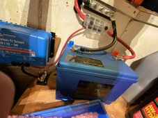
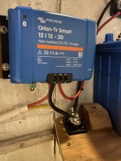
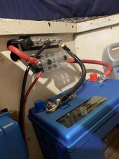
I've got a LifePO4 Windlass Battery that is totally separate (isolated) from the house LifePO4 bank. I use a DC/DC charger from main panel (house bank) to windlass battery. I originally installed a non-isolated Victron Orion DC/DC charger but was having problems popping the breaker at the panel because I was tying input ground to windlass battery ground. Fixed that and took out ground from DC/DC charger to windlass battery and now not getting charge to windlass battery. It reads 9.2V while the DC/DC charger is reading 13.2V input and 14.2V output. I think because there's no ground to complete the circuit back to charger? I've had different people tell me different things. One says "isolation has nothing to do with grounding issue" and another says, you need pos/neg input and pos/neg output from DC/DC charger to windlass battery. Probably difficult without pictures or schematics but thought I'd throw it out there for a better understanding of what I've got going on here. I tend to agree with the latter, that a complete, isolated circuit is necessary if you don't have a common ground for the whole system.
 
Could you please provide some type of circuit diagram? I am having a hard time following the description.
 
Sorry, FilterGuy, can't provide diagram at this time. Will try tomorrow. In the bigger picture, I'd just like a better understanding of the difference between Isolated and non-isolated DC/DC chargers and their application.
 
Sorry, FilterGuy, can't provide diagram at this time. Will try tomorrow. In the bigger picture, I'd just like a better understanding of the difference between Isolated and non-isolated DC/DC chargers and their application.
A Non-isolated DC/DC charger will share the negative between the input and output.
An Isolated DC/DC charger will isolate the input negative from the output negative.
Note: The positive is isolated for both the isolated and non-isolated DC/DC chargers.

Generally speaking,
* For a Stationary install in a house or cabin, a non isolated DC/DC is fine. (But you don't see DC/DC converters in stationary installs very often. )
* For an RV or van conversion where the engine and starter battery are in the same vehicle as the house battery system, a non-isolated is fine.
* For a trailer that wants to charge from the tow vehicle, it is usually best to have an isolated DC-DC charger.

This resource is not about Isolated vs non-isolated.... but it touches on the subject and showes at least one reason for using an isolated DC-DC charger for a trailer.

For the windlass described in the OP, a non-isolated should be fine,

1702878664257.png

Note: Many nonisolated DC/DC chargers have separate connection points for the input and output negatives, but they are tied together internally. I drew it this way to emphasize that they are the same circuit.

Note that in the above circuit, I do not show a connection to the chassis. However, in the boats I have worked on/around, there is always a bond someplace that ties all the metal parts of the ship together and the house negative is bonded to that.

An Isolated DC-DC would work as well:

1702879019842.png

I personally would probably treat the isolated DC/DC charger as a non-isoltated DC/DC charger and tie the input and output negative together. (I don't like the idea of floating DC circuits on a boat - No pun intended)
 
This is super helpful thank you! so the diagram you have with the non-isolated DC/DC is exactly the way we had it set up initially. The problem we were having was as soon as I powered on the charger the input voltage drops way down to 10V and automatically locks out (setting on Victron Orion). No idea why input was dropping so much.

Attached are two pictures of the original set-up we had. You can see the yellow neg from panel to small bus up to neg on DC/DC and then a black neg from bus up to windlass batt. This is the set up that wasn't working.

So my friend who is a pro marine electrician thinks we need an isolated DC/DC charger in this application as the windlass battery is completely separate from the house bank and everything else. My other friend, less experienced and more full of himself thinks non-isolated is fine. I guess in theory, according to the non-isolated diagram you included, we're effectively including the windlass battery into the common ground of the house bank as now all negative potential is tied together?
 

Attachments

  • Orion Non-Isolated 1.jpg
    Orion Non-Isolated 1.jpg
    106.8 KB · Views: 17
  • Orion Non-Isloated 2.jpg
    Orion Non-Isloated 2.jpg
    99.8 KB · Views: 18
FYI, the reason I have the small bus below DC/DC is that the yellow neg in and the black neg back out to windlass batt were too fat to fit into the GND port together.
 
I am going to say you definitely DO NOT want an isolated charger. An isolated charger means that ground potential of your house system and windless system will not be the same. This means that your windlass, and anchor chain, will be at a different potential from your prop and prop shaft. This could cause stray current corrosion that could destroy your prop in only a few days. Destroyed as in holes in it and a blade falling off. So whatever you do, don't use an isolated charger. An isolated charger is used in very special cases, and almost never on a boat for the reason I gave.

If I understand your first post, you have the DCDC on the positive wire from the house bank to the windlass battery. There is a ground wire from the house bank to the DCDC. And there is no wire connecting to the negative to the windlass battery. (there had been but you disconnected it because it popped a breaker) Where are you measuring 9.2V?

I suspect a wiring problem between the DCDC and the windlass battery, or with the windlass. What I would do is remove the windlass battery. Confirm it is within normal operating voltage (the BMS isn't in protection and it is adequately charged-does not need to be full) Set it right next to the DCDC, and connect it up, without any of the existing windlass wires. Just two short test wires to the battery. I think you will find it works fine. If not the DCDC should be tested.

The popped breaker sounds like a short to ground. The input voltage dropping to 10V could either be a short, or a poor crimp connection somewhere on the input wire between the DCDC and the house battery.

Do you have a bonding system on the boat? That connects all the metal bits, through hulls, windlass, etc. together? You might have a path to ground that you are not considering.
 
Thanks for this input Wholybee. I'll take all of it into consideration. There are a few things that I know for sure. Windlass is just fine. Connections between main panel (house bank) and DC/DC charger are fine. Actually all the connections are solid. If you look at the picture in my post above to FilterGuy, you'll see my original set up. Yellow neg from house bank to small buss under DC/DC. Black neg from same small bus up to GND port on DC/DC and then another black neg from same small bus up to windlass battery. Wondering if this is same as if I had yellow neg from panel and black neg to windlass batt shoved in the same GND port.

I'm getting 9.2V straight from the windlass battery. If I put one lead of meter on the small neg bus under the DC/DC charger and the other lead on any other pos in the system I get 13.2V. As soon as I move neg lead to another neg in downstream from DC/DC I'm back to 9.2V.
 
This means that your windlass, and anchor chain,
The windlass DC motor metal is not normally connected to the DC negative, the motor and metalwork are isolated.

If the windlass battery positive and negative are connected to the control relays the windlass should operate. ( disconnect from the DC to DC charger).

The issues point to faulty wiring in the route to the windlass, have the wiring of the windlass relays been checked ?

A point not discussed, is can the battery actually power the windlass without entering over current protection? Start up current will be much higher than running current.

Has the windlass operated previously, perhaps with a lead acid battery?
 
Last edited:
does the motor run without being connected to negative?
The windlass motor has windings isolated from the metal body of the motor. Its not like a car starter motor where the metal is negative.

Thus there is no electrical connection to the chain.
Screenshot_20231221-235443_Chrome~2.jpgScreenshot_20231222-000037_Chrome~2.jpg

Sorry just reviewed my post, left out the word metal, now corrected.
 
Thanks for this input Wholybee. I'll take all of it into consideration. There are a few things that I know for sure. Windlass is just fine. Connections between main panel (house bank) and DC/DC charger are fine. Actually all the connections are solid. If you look at the picture in my post above to FilterGuy, you'll see my original set up. Yellow neg from house bank to small buss under DC/DC. Black neg from same small bus up to GND port on DC/DC and then another black neg from same small bus up to windlass battery. Wondering if this is same as if I had yellow neg from panel and black neg to windlass batt shoved in the same GND port.

I'm getting 9.2V straight from the windlass battery. If I put one lead of meter on the small neg bus under the DC/DC charger and the other lead on any other pos in the system I get 13.2V. As soon as I move neg lead to another neg in downstream from DC/DC I'm back to 9.2V.
You picture looks correct. Adding the small busbar there is fine.

If you are measuring 13.2 V with the negative from the meter at the GND connection on the DCDC, but 9.2 when you move the wire to a point closer to the windlass, there is most likely an issue between those 2 points. Do you measure 13.2V or 9.2V with the negative wire on the busbar?

I would be very interested in the current flowing through the negative wire from the busbar to the windlass. Can you measure that? There is almost certainly a problem between the DCDC and the windlass. You could try disconnecting the DCDC, and the windlass, and measure the resistance of the wires (should be near 0 ohm) and between the negative and positive wires ( should be infinite or OL ) You can also measure from the negative on the house battery, to negative on the DCDC, and negative at the windlass. It should be 0V,(or very close) anywhere on the negative wiring. If you measure 4V (13.2V-9.2V) on a negative wire, then there is a problem somewhere.
 
The windlass motor has windings isolated from the metal body of the motor. Its not like a car starter motor where the metal is negative.
View attachment 184420View attachment 184421

You can't assume every windlass is that way, or that exposure to the environment will not cause leakage in time. I have to stand by the statement not to use an isolated windlass battery. Negative on the windlass battery should be the same potential as negative on the house battery.
 
Negative on the windlass battery should be the same potential as negative on the house battery.
Perhaps. In this case with a non isolated charger, yes the batteries should have common negative.
But there is no reason why the windlass battery and circuit should not be isolated, ( subject to using an isolated charger)
All circuits should be two wire , positive and negative. Main marine engine will have isolated starter/ alternator/ sensors, if not possible engine gearbox on isolated engine mounts and isolated coupling to prop shaft. Although through hull metal and prop shaft are bonded this bond should not include battery negative.
Where the hull is metal not having this isolation will cause issues, ( like holes in the hull).
 
Last edited:
I agree with you on an isolated engine, especially on a metal boat. Isolating an engine on a steel boat is mandatory. But that is different from isolating 2 batteries.

Consider a charger on shore, connected to a battery on a boat. The charger is connected to the power companies ground, and the boat is connected to water. That is the type of situation that should use an isolated charger, because there are already 2 grounds, and they are at different potential so current would flow through the water if you don't isolate. And that would quickly destroy a prop or other underwater metal if you don't have an isolated engine (most FRP boats do not have an isolated engine) But with 2 batteries on a boat, both negatives should be connected together. That avoids the situation of having 2 grounds at different potentials altogether. If you happen to have an isolated DCDC, connect both negative terminals together. I do that myself, on the DCDC on my boat.
 
hijack maybe. but related.

im using an isolated dcdc charger in my van (rolling sailboat?)

as far as i know, i dont have any sharing between my house system ground and the starter battery ground.
anything i have added to the house electrical goes to the negative house bus.

i dont have any problem to report.

or do i have a problem i am not aware of?
No problem, because your van isn't sitting in water, and doesn't have a connection to the physical ground beneath it. The isolated charger is not needed in your case, but it also does not hurt anything.
 
No problem, because your van isn't sitting in water, and doesn't have a connection to the physical ground beneath it. The isolated charger is not needed in your case, but it also does not hurt anything.
i have a ground loop on the starter battery side i was trying to find.
 
okay so the saga continues for those still interested;)

Just went back to drawing board. current photo is set-up WITHOUT black neg up to windlass batt bus. I've got 9.4V everywhere except when volt meter lead is on black neg on small bus underneath charger with DC/DC charger OFF, obviously. Obviously, with Isolated or non-Isolated I need a black neg from DC/DC to windlass batt. So, I put the black neg back in from small neg bus under charger up to neg bus to windlass batt. With charger OFF I now get 0.5V everywhere, which I sort of understand. As soon as I turn on charger and open Victron app it starts charging at 13.5V and then input voltage immediately proceeds to drop below threshold and charger shuts off until input voltage comes back up above 12.5 and then it starts the cycle all over again.

There is a direct run from panel all the way up to the charger with the same #8 two conductor cable I've had there for 10-15 years. Never an issue. They are securely connected to DC/DC charger but checked again today just to be sure and they are solid.

As for non-isoldated v. isolated in this application, I am comfortable with either after reading all the very helpful input here. But my concern is I may have other issues at play here, though I can't see what those are. It's got to be something simple that I'm just missing.
 

Attachments

  • setup .jpg
    setup .jpg
    206 KB · Views: 5
been reading of some other folks with RV setups having similar voltage drop issues. after all of this, I think the issue is the #8 cable from panel to DC/DC is insufficient. It's the same cable that's always been there yet it used to go to a Digital Echo charger for charging what was an AGM windlass battery. That Echo charger isn't nearly as demanding as the Victron Orion. Definitely not excited about pulling new thicker wires (#6) but that may be the ticket.
 
Back
Top