diy solar

diy solar

JK 4S BMS brand new with errors

I've found some STI3470 (SY8120) microchip.
As I understand it is some kind of similar chip.
 
Last edited:
Hello? I have JK-BD6A17S8P and the same problem (Protection (CPU AUX Anomaly)). I use it in battary for scooter. External Temp sensors have 9.4kOm, voltage to sensors 2V. I do not think it's sensors problem.
==============================================
help me find the cause, where to look? I think all bms are made according to typical scheme, please indicate where to look for the cause of the malfunction, thanks.
All power mosfets are - serviceable, I test it.
 

Attachments

  • IMG_20230805_200843.jpg
    IMG_20230805_200843.jpg
    183.6 KB · Views: 9
  • Screenshot_20230805-232818.png
    Screenshot_20230805-232818.png
    227.1 KB · Views: 9
  • Screenshot_20230805-232839.png
    Screenshot_20230805-232839.png
    265.8 KB · Views: 9
  • IMG_20230805_200846.jpg
    IMG_20230805_200846.jpg
    214.6 KB · Views: 8
  • IMG_20230805_204833.jpg
    IMG_20230805_204833.jpg
    113.9 KB · Views: 6
  • IMG_20230805_204828.jpg
    IMG_20230805_204828.jpg
    220.2 KB · Views: 5
  • IMG_20230805_204814.jpg
    IMG_20230805_204814.jpg
    263 KB · Views: 5
  • IMG_20230805_204739.jpg
    IMG_20230805_204739.jpg
    158.7 KB · Views: 6
  • IMG_20230805_200851.jpg
    IMG_20230805_200851.jpg
    203.4 KB · Views: 7
Last edited:
These chips are the likely culprit:

IMG_20230805_200851.jpg

You can replace these with a STI3470 (or JW5352M) and that should fix the CPU AUX Anomaly. Not sure why you have the "temperature sensor is abnormal" warning. That either means the sensor was disconnected when you took the screenshot, or the sensor is bad/badly connected.

You can PM me your address and I will send you some replacement chips. You do need some soldering skills with SMD components, preferably with hot air.
 

upnorthandpersonal Thanks for the quick response, those chips you marked are labeled (BCE1H). I would have been looking for what burned out for a long time, thanks for the prompt. We have where to buy them, yes, I have a lot of experience in soldering, thanks again, I’ll buy it and try to replace it.​

 
ordered these DC-DC after tomorrow should come. I measured the voltages incoming and outgoing from these DC-DCs, one comes out 3.3V from the other 4.5V. Something I haven’t met who needs 4.5V
 

Attachments

  • напряжения.jpg
    напряжения.jpg
    306.9 KB · Views: 9
I replaced the one that gave out 4.5V, nothing has changed. Then I calculated the volts, it turns out that all volts are correctly issued.

Vout=0.6*(1+R1/R2)
R1=104(100kOm)
R2=153(15kOm)

Vout=0.6*(1+R1/R2)= 4,6V
===================================


R1=683(68kOm)
R2=153(15kOm)

Vout=0.6*(1+R1/R2)= 3,3V
=============================
Do not know what to do now, maybe it's a reset button need pressed? but no buttons at all :(
 

Attachments

  • напряжения.jpg
    напряжения.jpg
    307.8 KB · Views: 1
I replaced 2 of them from one side - 1 and the other side - 1
S47Bcj4 - the new
=====================
1 year I use - enjpower-bms-3.7.4.88
but now I install - 极空BMS_4-9-2.apk , the last app what support android 6
 

Attachments

  • IMG_20230813_190514.jpg
    IMG_20230813_190514.jpg
    168.1 KB · Views: 6
  • IMG_20230813_190506.jpg
    IMG_20230813_190506.jpg
    171.9 KB · Views: 6
  • напр2.jpg
    напр2.jpg
    161.8 KB · Views: 6
Last edited:
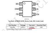
Ok, STI3470. That one should be fine. I would suggest replacing them all. One of the issues with the original chips in some versions was that they had a 500kHz chip instead of a 600kHz one, and that messed things up. I had a similar situation where the output voltage was fine, yet the issue was fixed replacing the component. I'm not saying this is definitely the case, but if you have them, worth a shot.

There could be another chip that needs to be replaced when this issue occurs. I need to go check my notes, it's been a while...
 
I think know the problem.
smd component marked as r3dlb. do not know what is it, can't find datasheet. But IN +3.3 , out 2.0V
but A13 Amplifier (lm321) need supply from 2.7
 

Attachments

  • 00front.jpg
    00front.jpg
    265.3 KB · Views: 8
  • 05back.jpg
    05back.jpg
    229.7 KB · Views: 8
  • problem.jpg
    problem.jpg
    51.3 KB · Views: 8
I soldered the diode instead of the LDO, now the A13 is powered by 2.9 Volts. But nothing has changed. I'll put this idea aside for now when I gain more strength =)
 

Attachments

  • IMG_20230818_173854.jpg
    IMG_20230818_173854.jpg
    360.5 KB · Views: 8
  • Screenshot_20230818-175333.png
    Screenshot_20230818-175333.png
    273.2 KB · Views: 7
I understood what happened, hk32f030mf4p6 was short of 3 volts, R3D is all working. I desoldered (hk32f030mf4p6) and 3 Volts was restored, signals from the T1 T2 go to hk32f030mf4p6. I don’t know if I can read (hk32f030mf4p6) and flash new one.
 

Attachments

  • 00front.jpg
    00front.jpg
    265.4 KB · Views: 8
  • 05back.jpg
    05back.jpg
    229.8 KB · Views: 8
  • ремонт.part2.rar
    13.9 MB · Views: 4
Last edited:
Back
Top